ASNARO-1 Satellite Overview
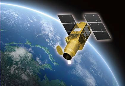
ASNARO, the Advanced Satellite with New system ARchitecture for Observation, is a Japanese satellite project developed by NEC Corporation and USEF (Institute for Unmanned Space Experiment Free Flyer) under funding from NEDO (New Energy and Industrial Technology Development Organization). The overall aim of the project is to develop a next-generation small-satellite bus with high-performance characteristics and flexibility to be able to support a number of payloads.
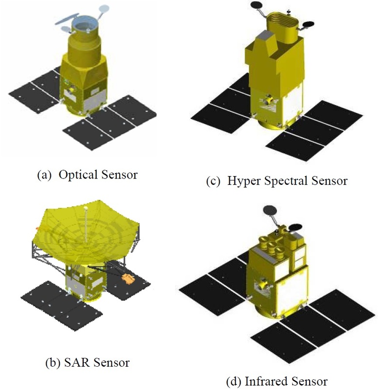
The ASNARO project was initiated in 2008 with the goal of developing a satellite bus with an open-architecture that reduces development and manufacturing cost while utilizing state-of-the-art technologies. ASNARO satellites will be employed in Earth observation missions, capable of supporting optical imagers, hyperspectral payloads and radar instruments. The ASNARO-1 satellite is outfitted with a high-resolution optical imaging instrument that can deliver imagery at a ground resolution of under 0.5 meters in the panchromatic band and under 2 meters for multispectral images.
The ASNARO-2 satellite will be equipped with an X-Band radar payload while ASNARO-3 carries a hyperspectral sensor.
NEXTAR Satellite Bus Applications
The NEC Standard Minisatellite Bus is the result of a joint JAXA/NEC study for the development of a highly adaptive satellite platform with a mass of under 500 Kilograms to be able to launch on small launch vehicle like Japan’s new Epsilon rocket. Named NEXTAR-100L, -300L and 500L, the satellite bus is available in different sizes but includes standardized mechanical, thermal, electrical and radio interfaces for easy manufacturing at low cost and short periods of time after being ordered. The development of NEXTAR also included the establishment of a ground system, data processing and product distribution solutions.
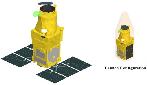
ASNARO satellites use the NEXTAR-300L satellite bus creating a total spacecraft mass of 495 Kilograms with 250kg allocated to the bus, 200kg reserved for the payload, and a nominal propellant load of 45kg. In its operational configuration, the satellite is 2.5 by 3.5 by 3.2 meters in size featuring two deployable solar arrays.
Each of the two solar arrays consists of three panels, using triple-junction gallium-arsenide solar cells to deliver a total power of more than 1,300 Watts that is delivered to an Array Power Regulator that performs step-down regulation, outputting 1,200 W of power. Power is stored in a Li-Ion battery unit consisting of 11 cells with a total capacity of 50 Amp-hours. State of charge of the battery is controlled directly by adjustments of the Array Power Regulator.
A Power Control Unit is responsible for changes made to APR operation for state-of-charge control. It also conditions the satellite’s main power bus and delivers electrical power to all subsystems of the satellite with bus protection. Actuation of drive mechanisms is also provided by the PCU that receives commands directly from the spacecraft computer and returns telemetry containing information on the health of the electrical system of the spacecraft.
The NEXTAR satellite bus is outfitted with a number of Attitude and Orbit Determination and Control Systems to ensure accurate navigation and precise pointing capability. The AOCS uses a central router that receives data from the spacecraft computer and delivers commands to the intended subsystem while providing telemetry from all systems that are connected to it via Attitude Control Interface Modules that are unique to each of the individual subsystems.
ASNARO-1 is equipped with three Star Trackers that acquire imagery of the sky that is analyzed by a software algorithm that compares the acquired star pattern with a catalog to precisely determine the spacecraft’s orientation in space.
A Coarse Sun Sensors determines the sun direction with medium accuracy to be able to provide pointing data to ensure good solar illumination of the solar arrays in the event of a spacecraft safe mode. Additionally, the CSS is used during initial attitude acquisition.
An Inertial Reference Unit is used to measure body rates and three-axis orientation in order to be able to reduce vehicle motion down to a level for acquisition by the Star Trackers that require small body rates to be able to start tracking star patterns. A GPS receiver is used for precise orbit and position determination.
Attitude actuation is accomplished with Reaction Wheels and Magnetic Torque Rods. The reaction wheel assembly is a rotating inertial mass that is driven by a brushless DC motor that spins the wheel. When accelerating the wheel, the satellite body to which the wheels are directly attached will rotate to the opposite direction as a result of the introduced counter torque. Four reaction wheels are used by the AOCS for three-axis control with redundancy, leaving one RW as spare.
Three Magnetic Torque Rods with redundant coils are used to create angular momentum by running a current through coils in the presence of Earth’s magnetic field. The torquers are regulated by computers that control the current that is passing through the coils in order to control the force generated on each axis. The magnetic torquers are used during momentum dumps and for attitude control in spacecraft safe mode.
ASNARO-1 uses a Reaction Control System consisting of four 3-Newton thrusters using Hydrazine monopropellant. The thrusters can be used for attitude control and momentum dumps, but their primary application will be orbit maintenance and adjustments, supplying relatively small amounts of delta-v to keep the spacecraft at its operational altitude of 504 Kilometers. The thrusters are fed from a single tank containing up to 45 Kilograms of propellant.
To support various payloads, primarily Earth observation sensors, the NEXTAR platform was designed to provide a high agility. Pointing of the satellite is possible to angles of +/-45 degrees along-track and off-track to be able to cover a large field of regard. The reaction wheels achieve a pointing rate of 1 degree per second and the overall pointing accuracy is better than 0.003 degrees with a high stability of 0.01degree/second.
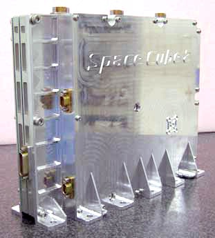
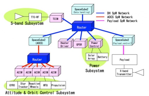
NEXTAR satellites use a SpaceWire data architecture that allows the transfer of data between the individual subsystems of the satellite, including the payload, at up to 400MBit/s per channel. The heart of the data and command handling system is the spacecraft computer. SpaceCube 2 was chosen as the main computer of the spacecraft. Developed by JAXA in 2005, SpaceCube 2 is a compact system capable of supporting all spacecraft functions.
SpaceCube 2 weighs under two Kilograms and is 7.1 by 22.1 by 17.8 centimeters in size drawing 14 Watts of electrical power. The system consists of three modules, a Central Processing Unit, a Data Recorder and Power Supply Modules. The CPU is a HR5000 processor chip that contains a 64-bit microcontroller based on MIPS 5kf architecture operated at a clock speed of 33MHz.
The Power Supply Modules receive the 28-Volt main bus of the spacecraft and generate voltages of 1.8, 3.3, 5.0 and 15 Volts for the operation of the various electronics. Internally, SpaceCube 2 uses PCI connections for data exchange with commanding provided from the communications system via an RS-422 analog bus. A total of eight SpaceWire channels can be supported by the system and ASNARO-1 uses two SpaceWire routers, one that connects the different subsystems to the main computer (TT&C, AOCS, Heater Controller, GPS, PCU and Payload Control) while the second is a dedicated AOCS router interfacing with the IMU, STT, RWA, MTQ and Propulsion controllers.
Internally, the SpaceCube 2 CPU includes 2MB of flash memory, 4MB Burst SRAM and 4MB of Asynchronous SRAM while the Data Recorder includes 1GB of SDRAM (2x512MB) and 1GB of Flash. ASNARO-1 uses a mass memory of 120GB to store acquired payload data, external to SpaceCube 2. The main computer operates on a Real-Time Operating System that is based on the TRON (The Real-time Operating system Nucleus).
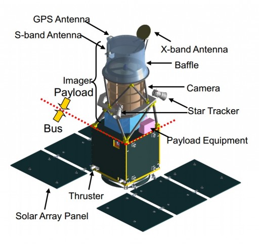
NEXTAR uses an S-Band Telemetry & Command System for command uplink from the ground and telemetry and housekeeping data downlink from the spacecraft. Payload data downlink is accomplished via a high-speed X-Band terminal that uses an antenna that is installed on a two-axis gimbal mechanism residing on the nadir-facing segment of the satellite payload. The Antenna Pointing Mechanism allows precise pointing of the X-Band antenna to track a ground station without moving the entire satellite which allows ASNARO-1 to continue observation tasks while data downlink is in progress which also enables the acquisition of real-time imagery.
The Antenna Pointing Mechanism has a mass of just 4.4 Kilograms including the antenna and supports rates of up to 4 degrees per second. Overall, the X-Band system achieves a data rate of 800 Mbit/s using a 16-QM modulation.
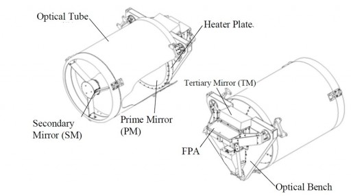
The main payload of ASNARO-1 is OPS, a high-resolution optical imaging payload using a pushbroom-type Three Mirror Anastigmatic design that, unlike the conventional Cassegrain or Ritchey-Chrétien systems, provides a larger field of view.
Overall, the instrument has a mass of 98 Kilograms consisting of a large optical baffle for sunlight and straylight rejection, an aperture cover, an optical bench facilitating the telescope mirrors and a focal plane assembly as well as associated control and data handling electronics that interface with the spacecraft bus.
Light entering the telescope aperture passes on the M1 primary mirror that reflects it to the secondary and tertiary mirrors that focus the light onto the Focal Plane Assembly and create the required focal length. The primary mirror is made of Silicon Carbide that provides excellent characteristics – high stiffness and extremely low thermal expansion. All telescope components are installed on a stable optical bench with favorable thermal characteristics.
The Focal Plane Assembly facilitates a CCD detector that uses Time-Delayed Integration and front end electronics that convert the analog read-out to a 12-Bit digital number that is transmitted to the Payload Interface Unit. The instrument covers the visible and near-infrared range of the spectrum.
The OPS instrument covers a ground swath of ten Kilometers and generates imagery at a resolution of under 0.5 meters in the panchromatic band and under 2 meters in six multispectral bands.
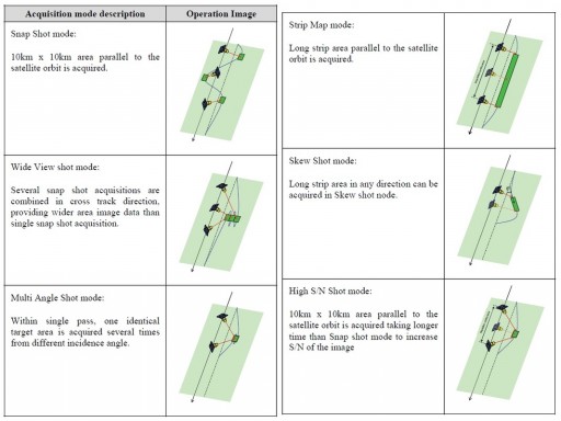
Operation of the payload can be accomplished in six different imaging modes. Snap-shot imaging creates 10 by 10-Kilometer images of targets along the ground track of the satellite up to 45 degrees to either side of spacecraft nadir. Wide-view shot mode combines several snap-shots in cross-track direction to cover a larger area on the ground while Multi-Angle Shot mode covers the same 10 by 10-kilometer area from different incidence angles. Strip-map mode results in long strips of images parallel to the satellite ground track with a nominal swath width of ten Kilometers and a maximum strip length of 850 Kilometers while skew imaging acquires image strips during spacecraft slew maneuvers. The final operational mode is a high S/N shot mode that allows for a better signal-to-noise ratio by using a longer integration time.
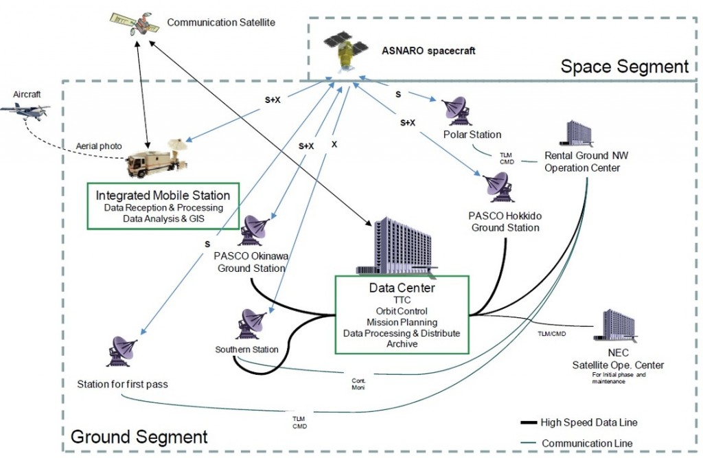
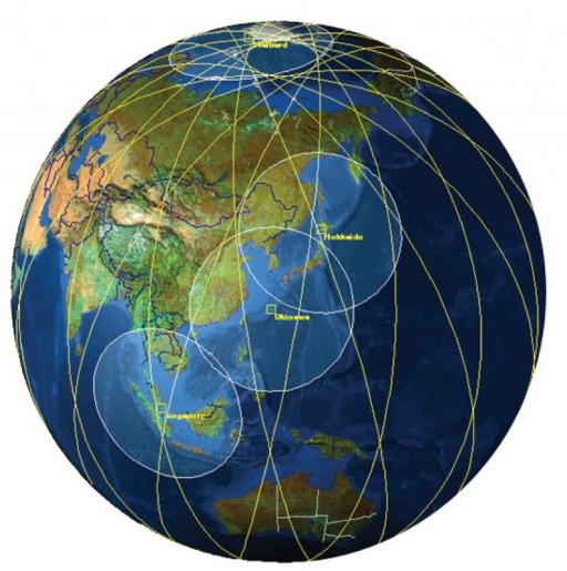
The ASNARO satellites use four ground stations – Hokkaido, Okinawa, Singapore and the polar station in Svalbard, Norway. Also, the mission established a design for a mobile ground station using a 4.6-meter dish installed on a truck to be able to downlink data from any location under the satellite’s ground track for operational application in disaster response and relief efforts.
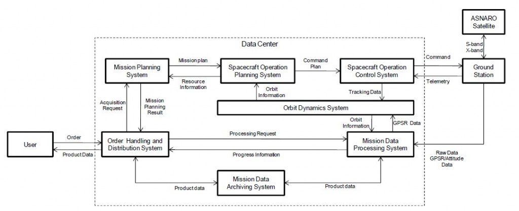
The ground segment of the ASNARO spacecraft has been designed to use a very high degree of automation in all areas including mission planning, data downlink, spacecraft maintenance, data processing and data distribution. A central data center receives imaging requests from customers, automatically generates a mission plan taking into account spacecraft sequences and weather conditions at the requested imaging site to ensure cloud-free imagery is acquired.
The mission plan is uplinked to the satellite several times a day to be able to support imaging on short-notice. Imagery is downlinked from the satellite to one of the ground stations which then relays the data stream to the data center in real-time for an automated processing sequence that delivers calibrated, geometrically corrected, high-resolution images within three minutes of acquisition and digital elevation models and digital surface models within five minutes for distribution to users via the Internet.
Data Processing & Distribution Architecture