All-Star/THEIA
The full name of the All-Star/THEIA mission is Agile Low-cost Laboratory for Space Technology Acceleration and Research / Telescopic High-definition Earth Imaging Apparatus. It is a project of the Colorado Space Grant Consortium (COSGC) and Lockheed Martin.
The objective of the project is to develop and test a new high-performance three-unit CubeSat platform that can be outfitted with different payloads for operation in Earth orbit. The bus includes satellite structures, power, communications, attitude determination and control, command and data handling, and position knowledge systems as well as payload interfaces (structural, power, data) with simple and quick integration.
The satellite follows a simplified design in which all subsystems have identical electrical interfaces and the same interfaces with the Command Handling and Data System. All-Star uses the 3U CubeSat form factor and is 10 by 10 by 34 centimeters in size with a mass of 4 Kilograms. The payload can occupy one CubeSat unit with a maximum mass of two kilograms.
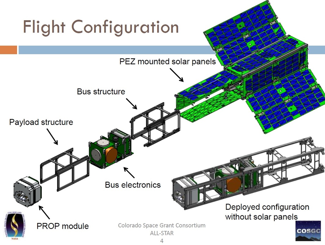
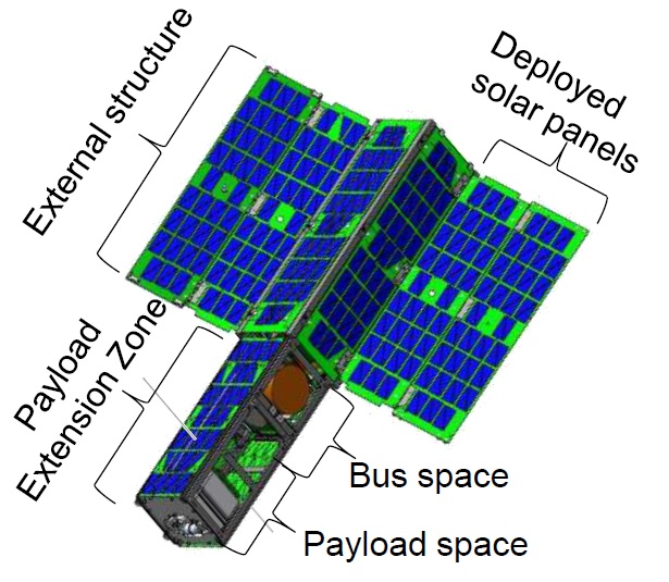
The satellite is comprised of three sections – a payload section, the satellite bus and the Payload Extension Zone with External Solar Panels.
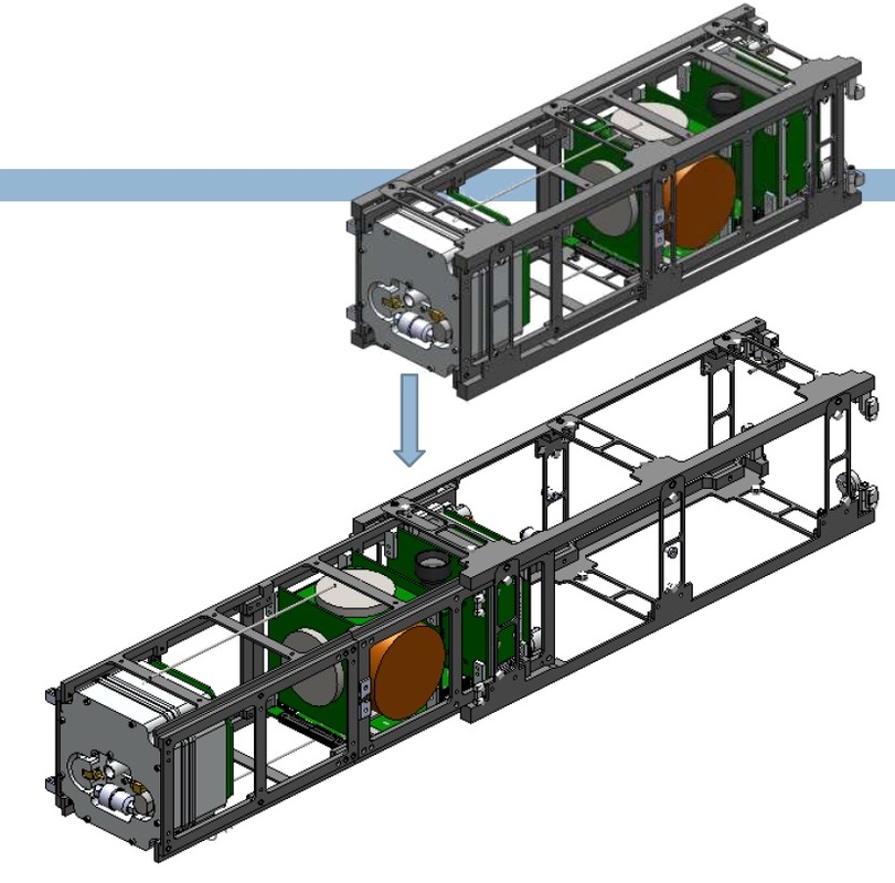
The solar panels are restrained during launch using fixed clips on the internal structure that hook into brackets on the outermost solar panel while the Payload Extension Zone is secured by a mini-Frangibolt actuator that is fractured for deployment. Two constant force springs allow the PEZ to be deployed via smooth sliding interfaces that allow the springs to extend to reach the fully deployed configuration that uses locking mechanisms to rigidize the satellite structure. The satellite uses two solar arrays with two panels each as well as body- and PEZ-mounted solar cells. A total of 918 solar cells are installed on the spacecraft and power-generation is optimized by Maximum Power Point Tracking.
The Electrical Power System provides a nominal power of 5 Watts to the satellite bus and 5 Watts to the payload using two buses at 12 V and 3.3 V. A peak power of 30 Watts during communications passes can be supported. Power storage is provided by four Li-Ion Battery cells with a cell capacity of 2.6 Amp-hours.
The satellite bus is outfitted with a fairly complex Attitude Determination and Control System rarely seen in a CubeSat.
Satellite Block Diagrams: Electrical Power System (left) & Attitude Determination & Control System (right)
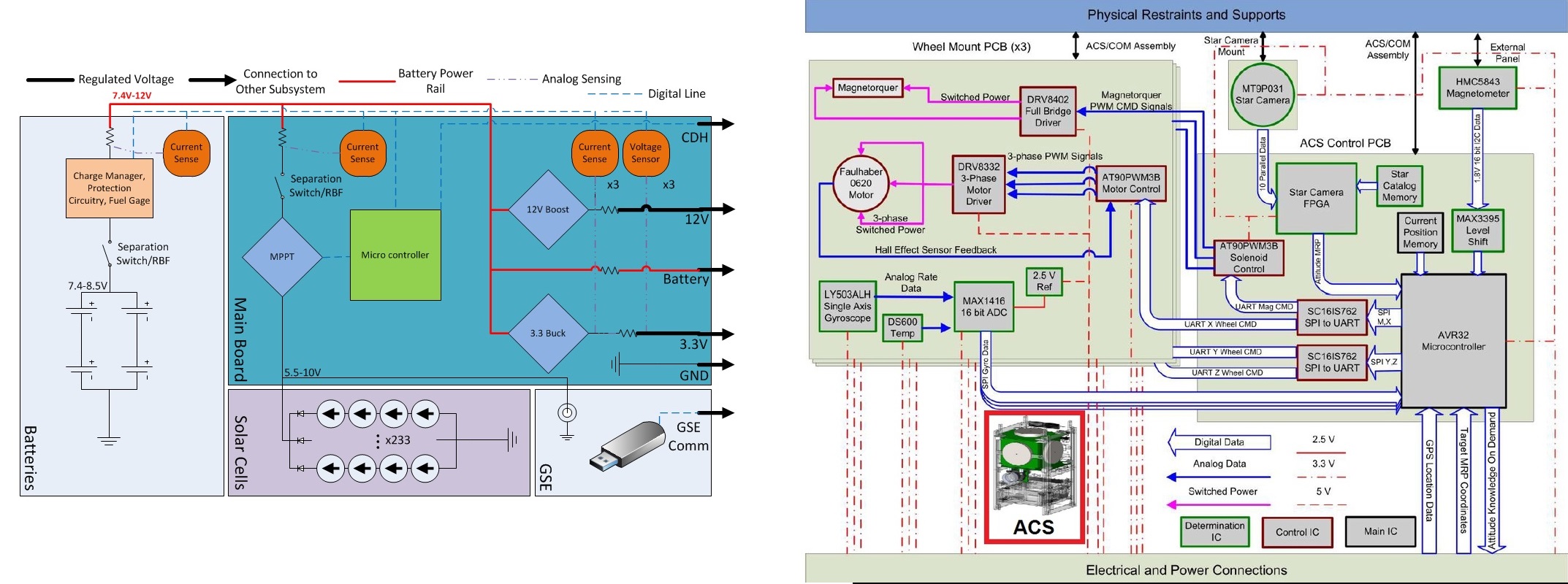
The three-axis attitude of the spacecraft is sensed by a 3-axis magnetometer, a star tracker, and gyroscopes. Attitude actuation is provided by a reaction wheel assembly consisting of three wheels and a magnetic torquer that is used for momentum dumps. The ADCS equipment is controlled by a AVR32UC3 microcontroller. A GPS receiver provides orbital positioning data and timing solutions for use by other onboard systems.
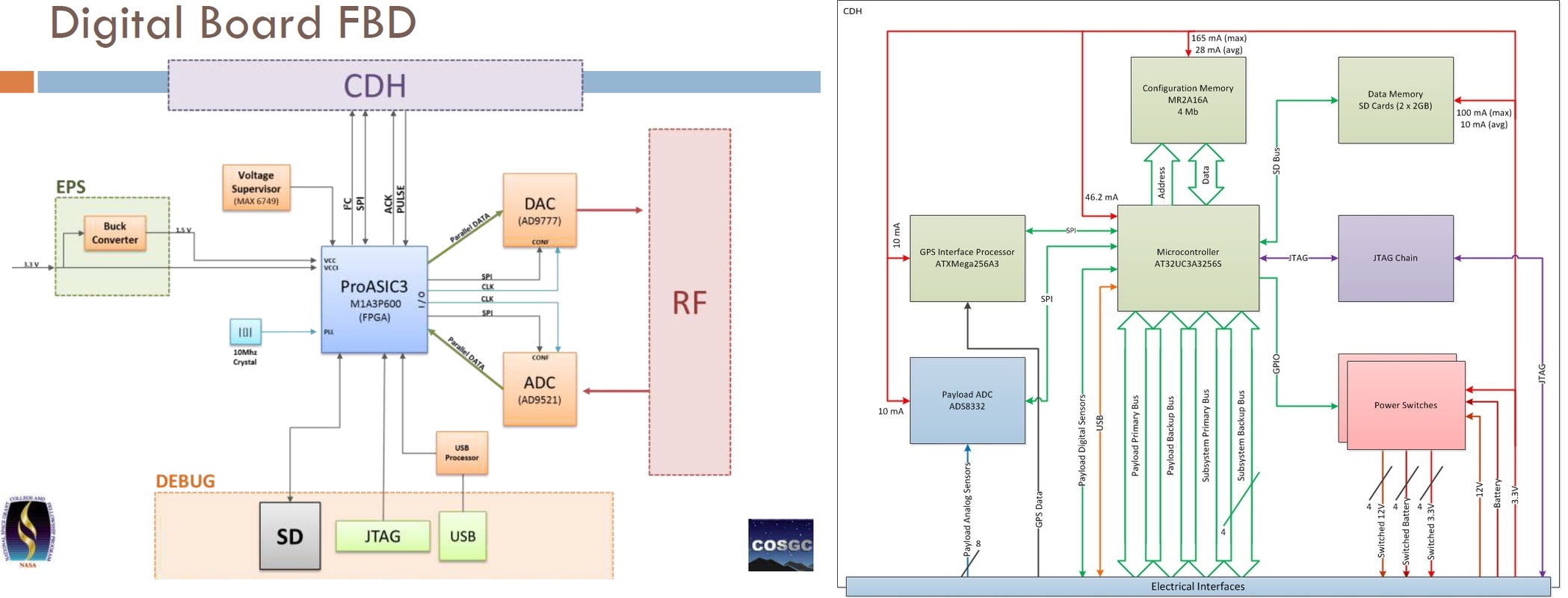
The Command and Data Handling System uses a wire-free design approach featuring a backplane with slots for the individual subsystem cards. A 32-bit microcontroller runs the flight software while an 8-bit controller is used to support power-switching components and GPS. MRAM (Magnetoresistive Random-Access Memory) and SRAM (Static Random Access Memory ) extensions are supported as well as Micro-SD Cards for data storage.
The Communications System of the satellite provides flexibility through the use of software defined radio that can be reprogrammed for different applications and allows reconfigurations in flight. Data downlink is accomplished in S-Band at a rate of 250 kbit/s. Uplink uses the amateur UHF Band at 435 MHz achieving a data rate of 9.6kbit/s.
All-Star can support an optional propulsion system. Utilizing a Cold Gas Propulsion System, the satellite would carry butane in a liquid tank that is supplied to a heated gas tank connected to the nozzle that uses a solenoid valve. The system would achieve a thrust of 0.05 Newtons for a total delta-v budget of 10 meters per second or more.
Satellite Block Diagrams: Command/Data System (left) & Comm System (right)
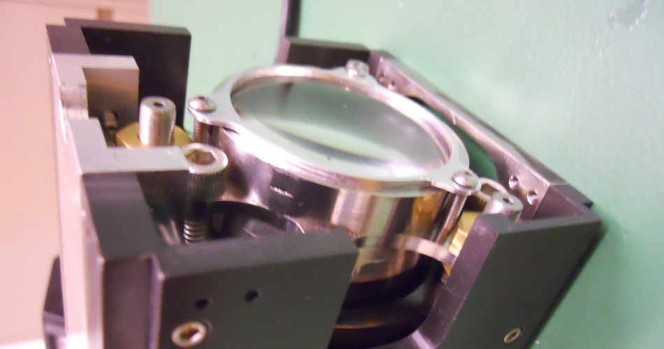
For its first flight, All-Star is equipped with the THEIA payload. This optical remote sensing payload will acquire full-color images of Earth to verify all capabilities of the All-Star Satellite Bus as part of its proof-of-concept mission. The dual-element instrument structure uses elements of Invar-36 and Titanium-64 to match the thermal expansion and compression characteristics of the optics. The 50-millimeter aperture uses four light baffles to eliminate off-axis light.
THEIA uses a refractor and a CMOS imaging sensor. The refractor is a 50.8mm achromatic doublet lens with a focal length of 150mm. The CMOS imaging board is placed at the focal point of the optics. The 5-megapixel detector operates at wavelengths of 400 to 1000 nanometers to capture full color images. THEIA has a field of view of 1°.
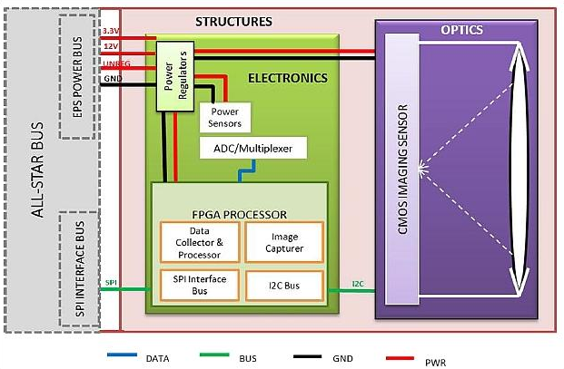
THEIA is equipped with its own electronics that use the All-Star power bus that is regulated and distributed to the CMOS imaging board and the FPGA processor unit and support electronics such as sensors. Images are captured as part of commanded sequences that use the All-Star Attitude Control System to re-orient the satellite to chosen imaging targets before capturing the image with the electronic shutter of the sensor.
The raw image is then sent to the FGPA via the I2C interface for image processing and transfer to the Data Handling System of the Satellite via an SPI interface. Downlink of the images is done by the spacecraft. The satellite can take one image per minute.