
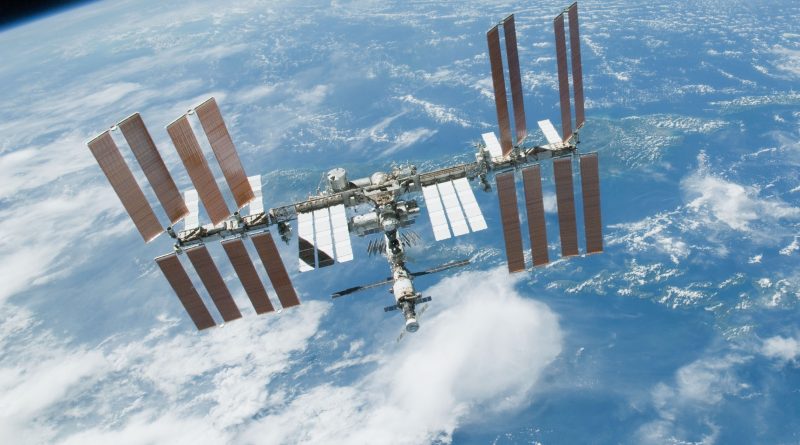
Space Station suffers partial Loss of Power, Mission Control evaluates Recovery Options
The International Space Station suffered a partial loss of power on Friday when a short in an electrical system caused one of eight power channels of the Station to go offline.
A switching box feeding power from one of the Station’s eight solar array wings tripped due to a short in the 1B power channel, leading to a loss of a number of systems on ISS. There is no immediate danger to the crew and systems are expected to be restored later on Friday by connecting them to another power channel. However, it will take Mission Control several days to diagnose the 1B issue, according to information passed to the six crew members on board the orbiting complex.
The trip in Direct Current Switching Unit 1B occurred around 18 UTC on Friday and knocked out one eighth of the Station’s total power, taking down one power channel. With one channel down, ISS still has seven good power supply channels which can carry all loads, permitting nominal operations to continue after loads have been re-balanced. A power management plan may be implemented to ensure margins for the individual channels are being protected, but all essential systems will receive continuous power.
The Direct Current Switching Unit trip was the result of a short circuit upstream of the DCSU, likely within the Sequential Shunt Unit. The system responded as intended, cutting power to protect downstream equipment from damage. Mission Control shunted power coming from the 1B Solar Array Wing to avoid feeding power into a shorted system and began working on a forward plan.
The crew was informed that several redundant Multiplexers/Demultiplexers – the Station’s command and control computer systems – were no longer powered, cutting redundancy for commanding and telemetry. The Node 3 Common Cabin Air Assembly and the Oxygen Generator Assembly were also affected by the loss of power. Additionally, several Audio Terminal Units on ISS became unavailable and a number of other redundant systems went down with no immediate impact given the fault-tolerant design of the overall ISS system.
As a direct measure to restore power, Mission Control will tie loads from the 1B channel to 1A which can carry additional loads without issue, allowing essential systems to be operated. Mission Control will be busy throughout the overnight hours (UTC) recovering the various systems in this alternate configuration.

Diagnosing the location and signature of the short and coming up with a plan for the recovery of the 1B power channel will take several days, Mission Control told the crew later on Friday.
Telemetry data will be used to trace back the system that shorted out. The Electrical Power System delivers plenty of telemetry to Mission Control, allowing an in-depth study of the signatures coming from the DCSU and upstream/downstream systems. Mission Control will study currents in the individual power circuits and also look at thermal signatures which in the past served as indicators for failures that may not be recoverable through ground commanding.
The 1B DCSU is located on the outermost truss segment on the starboard side of ISS (S6) and plays a critical role in passing power coming from the solar array to the station’s power routing boxes and eventually to the different users. A situation where one ISS power channel is down is far from critical, but Mission Control will aim to recover from this issue in a timely manner given the loss of redundancy.
A similar issue when a Sequential Shunt Unit upstream of a DCSU suffered a short in one of its capacitors occurred in 2012 in the 3A power channel causing a DCSU trip. After measurements, it was determined that the Sequential Shunt Unit was still functional and the Remote Bus Isolator was commanded to close, restoring the power channel. When the short recurred in 2014, the system could not be recovered remotely and a spacewalk for the replacement of the Sequential Shunt Unit was necessary.
.
ISS Electrical Power System Overview
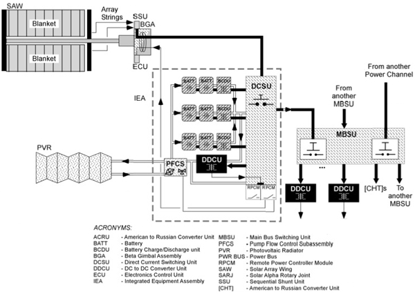
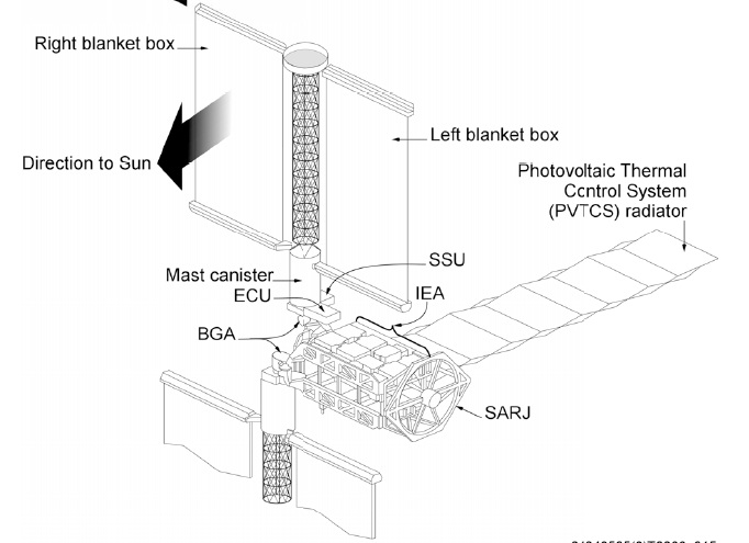
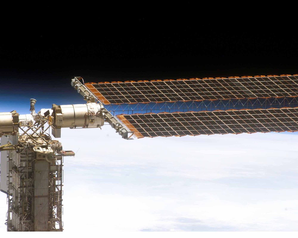
The ISS electrical power system consists of power generation, energy storage, power management and distribution equipment – short: PMAD.All USOS (United States Orbital Segment) power is generated by the Space Station’s eight Solar Array Wings that build the photovoltaic electric power generation subsystem consisting of eight power channels, one for each array. One PV Module (Photovoltaic Module) consists of two solar arrays with each wing being 35 meters long and 12 meters wide.
There are 32,800 solar cells on each power channel, 400 of those are connected in series to form a string with 82 strings being connected in parallel. Each of the individual channels features Nickel-Hydrogen Batteries that are charged when the Solar Array Wings are exposed to sunlight and are discharged when the Station is making a night-pass or when additional power is required on-board.
When in sunlight, the Solar Arrays are continuously pointed at the Sun by computer controlled sun tracking capabilities that are realized by one Beta Gimbal Assembly located on each PV Module that rotates the wing, while a single Solar Alpha Rotary Joint is used to rotate four arrays on one side of the truss all together. Before power generated by the Solar Arrays enters the rest of the electrical system, it has to pass Sequential Shunt Units (SSU) that regulate the power coming from the arrays at an established setpoint of 160 volts.
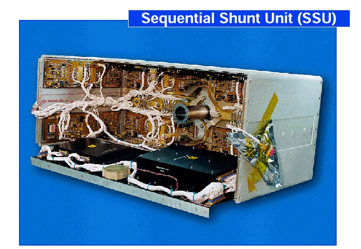
The SSU receives power directly from the array and maintains the specified output voltage by shunting and un-shunting strings on the array as the output power of the SSU is the sum of all connected strings. When the SSU output power exceeds the current power demand of ISS systems and batteries, the bus voltage begins rising which triggers the SSU to begin shunting strings to reduce power output. A dropping bus voltage triggers the SSU to un-shunt strings. The SSUs are located on the Beta Gimbal Platform, at the bottom of the Mast Canister Assembly and houses circuit boards required to shunt the strings as well as ramp generators and other boards to ensure a steady power output.
Responsible for managing the primary power coming from the Solar Arrays (actually from the SSUs) are Direct Current Switching Units – DCSUs – which control initial power distribution and provide bus protection. During orbital day, the eight DCSUs send a portion of the primary power to the Station’s MBSUs to go to the users while the other portion of the primary power is transferred to BCDUs – Battery Charge/Discharge Units that control the charging and discharging of each of the batteries – managing the available battery power.
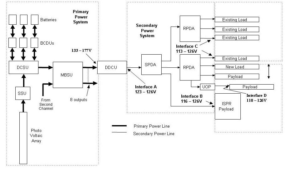
A DCSU consists of six high-powered switches that are normally in a closed position to allow power to pass from the source (solar arrays or batteries) to downstream users. These switches are known as Remote Bus Isolators and allow a bidirectional flow. The RBIs are electromechanical relays that transfer power between EPS components and the DCSU primary bus.
Allowing for bidirectional current flow, the RBIs allow power to be passed to the SSUs during night and transfer power to and from the batteries. The RBIs protect the power bus by tripping in overcurrent conditions, taking all downstream systems off the bus. The individual RBIs can be commanded between their opened and closed positions via commands sent from the ground.
During night passes when no new power is generated by the solar arrays, power is sent from the Battery Charge/Discharge Units back to the Direct Current Switching Units which then passes it along to the Main Bus Switching Units. Space Station primary power operates at a voltage range of 137 to 173 volts direct current.
There are four Main Bus Switching Units aboard the Space Station, all of them are mounted on the S0 Truss Segment and each one is fed power from two of the power channels. So, MBSU-1 receives power from channels 1A and 1B, while MBSU-2 receives primary power from channels 2A and 2B, and so on. Both, MBSUs and DCSUs use a network of high power switches to direct the power flow. The RBI network is used to isolate power paths and distribute loads to other channels in case of failures.
Each MBSU distributes power from its two associated channels further downstream where conversion to secondary power occurs. DC to DC Conversion Units, DDCUs, convert ISS primary power to a stable 124.5V DC power supply for all other EPS components.
One final component in the EPS string are Remote Power Control Modules (RPCM) which contain circuit breakers. From the RPCMs, power is routed to equipment of the Space Station.
MBSUs also route primary power to the Russian Service Module, where equipment is located that is needed to integrate the Russian System which is working with 28V DC power into the USOS power supply. At the Service Module, primary power is converted to Russian Secondary Power via the American to Russian Conversion Units (ARCUs). Power provided by the ARCUs is then routed inside the Russian Segment to users requiring the 28V DC bus voltage. There are also Russian to American Converter Units (RACUs) for the reverse conversion process.
