
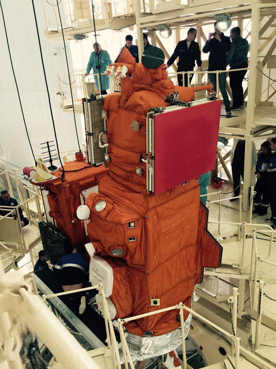
Lomonosov Satellite (MVL-300)

Mikhailo Lomonosov, also known as MVL-300, is a Russian Astro- and Geophysics satellite named after 18th century scientist Mikhail Vasilyevich Lomonosov. The spacecraft, operated by Moscow State University, is outfitted with seven instruments for a range of measurements including X- and Gamma-Ray detection, charged particle influx, radiation dose, and electromagnetic fields.
The overall goal of the mission is to study extreme physical processes in the high-energy regime, occurring in the atmosphere, near-Earth space and the far reaches of the universe. For that, the spacecraft is outfitted with a range of sensors, capable of detecting high-energy radiation and particles. The mission is operated by Lomonosov Moscow State University with support of six other institutions within education, research and industry in Russia. International partners of the mission come form South Korea, Denmark, Spain, Mexico, Taiwan and the United States.
The goals of the Lomonosov mission are to study cosmic rays in the high-energy regime near the energetic spectrum cutoff, examine the characteristics of gamma-ray bursts in the universe by simultaneous spectral analysis and imaging in UV/VIS, study Transient Luminous Effects in Earth’s atmosphere triggered by different mechanisms, and study Earth’s magnetosphere and near-Earth radiation environment using different detector systems.
The 645-Kilogram MVL-300 satellite was built by NPO VNIIEM based on a surplus satellite platform from the Kanopus-V and BKA satellite projects. Contracted for the development of the Kanopus satellite platform, NPO VNIIEM elected to work with Surrey Satellite Technology Ltd. based in the United Kingdom given their experience with small satellites. Under the contract signed in 2007, SSTL is delivering three suites of satellite avionics and software plus technical support, electrical power management and batteries, onboard computers and data handling systems. The company will also provide spacecraft assembly and integration support.
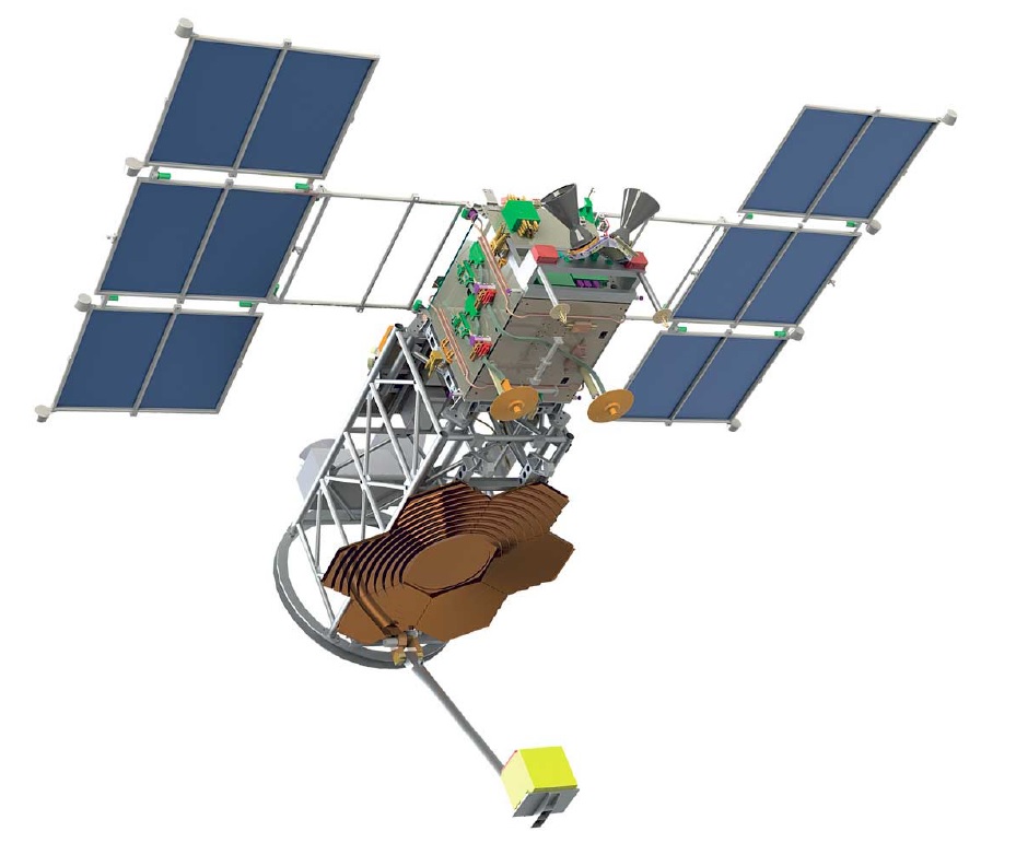
The Kanopus satellite bus hosts a deployable solar array with an average power supply of 300 Watts. The spacecraft host precise attitude determination and control systems featuring star trackers, sun sensors, and inertial measurement systems for attitude determination and reaction wheels as primary attitude actuators. The satellite platform supports precise pointing with an attitude stability of 0.001 degrees per second and an agile attitude actuation system for fast slews between observation targets.
The Kanopus satellites have an onboard memory of 24 gigabytes. Data downlink is accomplished using an X-Band communications system operating between 8.048 and 8.382 GHz and achieving data rates up to 122.8 Megabits per second.
The MVL-300 satellite hosts seven scientific and technical demonstration payloads for a total mass of 120 Kilograms. The payload aims to conduct a simultaneous study of gamma-ray bursts by means of optical detectors and gamma-ray detectors as well as the study of transient phenomena in Earth’s atmosphere.
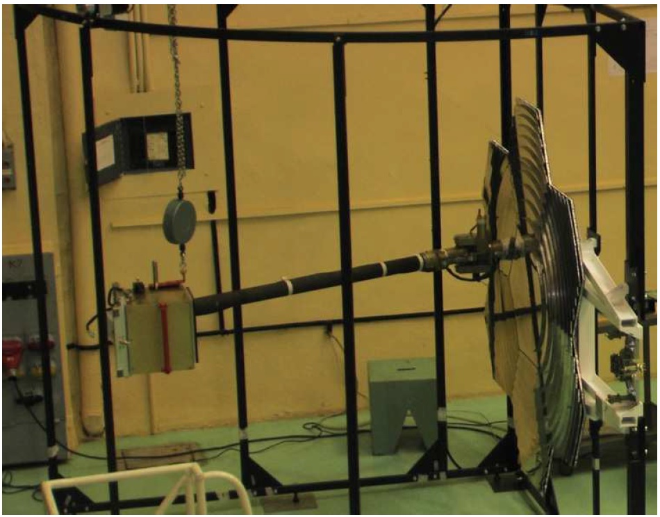
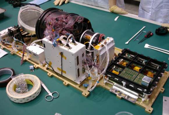
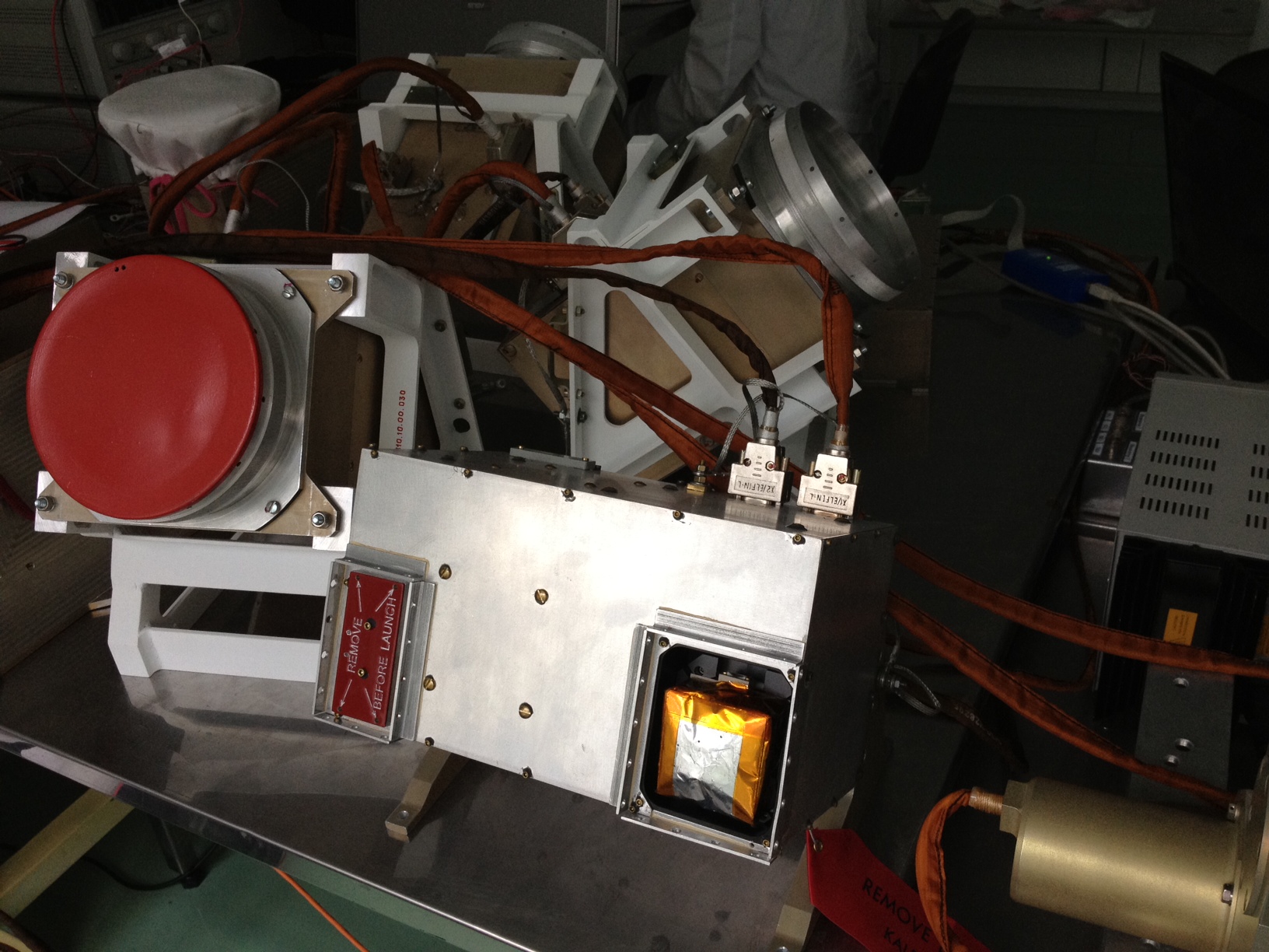
The primary instrument of the MVL-300 satellite is the Tracking Ultraviolet Setup (TUS) – originally planned to fly on a dedicated mission to conduct measurements of fluorescent light generated by Extensive Air Showers of Ultra High Energy Cosmic Rays in Earth’s atmosphere.
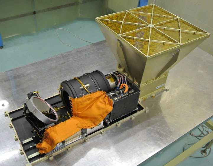
The 60-Kilogram TUS instrument employs a large Fresnel-type mirror-concentrator to collect UV radiation over a two-square meter area and feeding it to a photo-receiver placed in the focal plane of the concentrator, 150cm from the mirror. The photo-receiver consists of 256 photomultiplier tubes and can be moved relative to the concentrator based on the operational mode of the mission, typically generating a spatial resolution for UV imaging in the atmosphere around five Kilometers.
A solar light sensor functions as the main safety device of the instrument, triggering the Photo-Receiver Moving System to fully remove the receiver from the mirror focus to avoid damage by direct solar radiation.
The Fresnel-type mirror-concentrator is comprised of a central parabolic mirror element and 11 parabolic rings focusing a parallel beam onto the focal plane. The mirror segments are 3 centimeters thick and cut to a hexagonal shape with a 66-centimeter diagonal. The segments are made of carbon plastic with aluminum honeycomb reinforcements, also providing favorable thermal expansion characteristics. With a total mirror area of 2m², the instrument has a field of view of +/-4.5 degrees.

The Photo Receiver comprises 256 photomultiplier tubes arranged in a 16 by 16 grid to create a spatial resolution of 5 x 5 Kilometers. Each pixel contains a single 13-mm multi-akali cathode PM tube with a 240-400 nanometer bandpass. Analog signals from each PM tube are fed to an analog-to-digital converter for 10-bit digital conversion and signal integration. Signals from UHECR (Ultra High Energy Cosmic Ray) events are collected every 0.8 microseconds to select EAS (Extensive Air Showers) signals from other, slower events types such as Transient Luminous Events and micrometeors.
The TUS instrument uses a two-stage identification system for relevant EAS events – the first stage is triggered when an event in a single pixel is above a set threshold and the second stage is triggered when at least three neighbor pixels are triggered or when signals in one pixel are stronger in three sequential time intervals. Other triggers are in place to identify slower events with higher integration times to also capture science data on dust grains, meteors and TLEs.

The BDRG instrument (Block for X-ray and gamma-radiation detection) is capable of detecting gamma-ray sources in the sky and record their spectral signatures while also triggering their optical observation with the ShOK instrument. The instrument is comprised of three detectors and a common electronics box.
Each detector has an active area of 36cm² and covers and energy range of 0.01 to 3.0 Mega-Electronvolts. BDRG can localize gamma-ray sources with an accuracy of 1 to 3 degrees and is expected to observe around 100 sources per year. Each optical head has a mass of 7 Kilograms and the instrument draws 7.5 Watts of electrical power during operation.

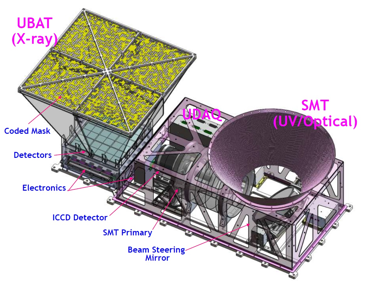
UFFO, the Ultra Fast Flash Observatory, is a two-part instrument comprised of a UFFO Burst Alert Telescope (UBAT) and a Slewing Mirror Telescope (SMT) to capture X- and Gamma-rays. The UBAT instrument, covering an energy range of 5 to 2000 Kilo-Electronvolt, is responsible for gathering data in the gamma-ray regime and to deliver pointing data to the SMT to be quickly pointed to the source location to capture UV/VIS imagery of the gamma-ray afterglow phenomenon.
UBAT uses a coded mask aperture camera with a field of view of 90.2 x 90.2 degrees using an LSO-MAPMT Detector System (Lutetium oxyorthosilicate Multi Anode Photo Multiplier Tube) with 48 by 48 pixels. Each pixel is 2.88 by 2.88 millimeters in size and 2mm in depth, creating an effective detector area of 191cm². Imaging is accomplished by placing a pinhole mask over the detector array so that the shift in the shadow pattern can be put through a deconvolution procedure to encode the location of the X-ray source in the sky. UFFO’s detectors deliver an energy resolution of 2keV and a localization accuracy of gamma-ray bursts around 10 arc-min.

The Slewing Mirror Telescope is comprised of an optical baffle, a Beam Steering Mirror to select the imaging field of view, and a 20-centimeter Ritchey-Chretien telescope consisting of a specialized Cassegrain Telescope using a hyperbolic primary mirror and a hyperbolic secondary mirror to eliminate third-order coma and spherical aberration. RCT designs are well-suited for wide-field and photographic observations with good off-axis performance at a large field of view free of optical errors.
The Slewing Mirror Telescope has an instantaneous field of view of 17 by 17 arcmin and the Beam Steering Mirror covers a 70 x 70-degree sector from which the FOV can be selected.
SMT is sensitive for wavelengths between 200 and 650 nanometers using a 256 x 256-pixel CCD detector element. This creates a 4-arcsec pixel scale and the instrument achieves a location accuracy of 0.5 arcsec. One major design driver for the SMT instrument was agility to be able to respond to gamma-ray triggers in one second or better. The Slewing Mirror is capable of traversing across its entire field of view in just over one second and requires a settling time of maximal 330 milliseconds, allowing it to reach most locations within one second to the trigger arrival from UBAT. The electronic latency for the trigger calculation has been reduced to 0.1 second using advanced algorithms.
The UFFO instrument assembly measures 98 by 41 by 38 centimeters in size and weighs 22 Kilograms. During operation, it consumes 25 Watts of electrical power.
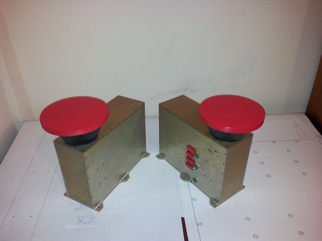
ShOK, the Optic cameras of super-wide field of vision, comprises a pair of stationary wide-angle cameras. Each camera assembly consists of an Optical Head and a dedicated electronics unit in charge of image processing.
The instrument has a field of view of 20 x 40 degrees and can image targets down to Mag 11. ShOK acquires frames every 0.2 seconds and imagery is stored on board for a specific period of time before being overwritten.
In case a Gamma-Ray Burst trigger occurs, all ShOK imagery from one minute before until two minutes after the trigger will be prepared for downlink, amounting to 700MB of data per event.
DEPRON, the Dosimeter for Electrons, Protons and Neutrons, is a combined instrument for radiation monitoring and flux measurements for charged particles. The instrument measures 28 by 16 by 8 centimeters with a mass of 3 Kilograms and a power demand of 5 Watts. Measurements completed by DEPRON include absorbed radiation dose, linear energy transfer spectra for high-energy electrons and protons, and the detection of thermal and slow neutrons.
The DEPRON instrument consists of a charged particle dosimeter using a semiconductor detector element, a gas-discharge counter for the measurement of thermal neutrons and support systems comprised of analog-to-digital conversion electronics, data handling and power supply.
ELFIN-L is the Electron Loss and Fields Investigator for Lomonosov – a joint project of the University of California Los Angeles and Lomonosov Moscow State University. The instrument consists of a Flux Gate Magnetometer (FGM), an Energetic Particle Detector for Electrons (EPDE), and an Energetic Proton Detector for Ions (EPDI).
The primary objective of the instrument is to identify and understand the dominant mechanisms in the loss of energetic electrons and ions in order to better assess hazardous areas in near Earth space for satellites and human spaceflight.
The EPDE Energetic Particle Detector Electrons consists of eight stacked 1000-micrometer thick and two 500µm tick Silicon Solid State Detectors. Atop the detectors sits an aluminized Lexan foil to reject protons up to an energy of 500keV. EPDE measures electrons at energies of 50keV to 4MeV.
EPDI, optimized for measuring ions, contains two 1000-micrometer thick detectors and a samarium cobalt magnetic deflector to remove low-energy electrons from the detector inflow. The front detector measures ions up to 50keV while the second detector is sensitive up to 500keV using an anti-coincidence logic to disregard high-energy electrons.
Both EPDE and EPDI are encased in a 1.2-centimeter thick aluminum-tantalum vault to shield the non-detector sides from incoming particles. The combined EPDE/EPDI suite weighs 1.5 Kilograms and measures 8.5 x 8.0 x 8.0 centimeters in size.
The overall principle of the Flux Gate Magnetometer (FGM) is making use of the nonlinearity of magnetization properties for the high permeability of easily saturated ferromagnetic alloys to serve as an indicator for the local field strength. The ferromagnetic material is surrounded by two coils of wire – one coil runs an alternating electrical current which drives the core through an alternating cycle of magnetic saturation. This changing field induces a current in the second coil which can be measured by a detector.
In a magnetically neutral environment, the input and output currents would be identical, but the presence of an external field leads to an easier saturation of the core when in alignment with the core while saturation is less easily achieved when the core is exposed to an opposing field.
This leads to the output current becoming out of step from the input which, with the known parameters of the core material and the simultaneous measurement of the input, will provide information on the local field strength using known calibration data.
IMISS-1 is an auxiliary payload flying on the MVL-300 mission to test the performance of a microelectromechanical inertial measurement sensor in the space environment for potential future application in crewed spaceflight for the improvement of target recognition and gaze stabilization in Cosmonauts. IMISS-1 houses micro gyros and accelerometers to deliver linear acceleration and angular rate data.
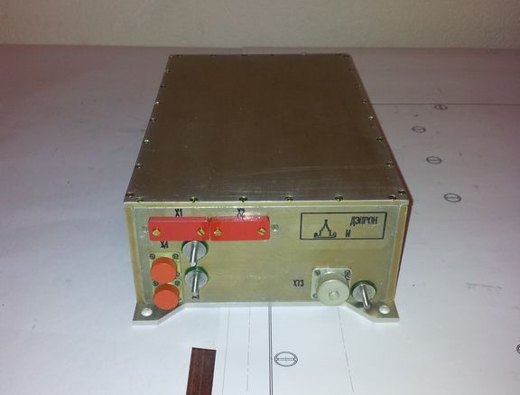
All of MVL-300’s payload systems are controlled from a central Information Unit which is in charge of executing commands to switch instruments on and off and transition instruments between operational modes. It also accepts status telemetry and science data from the instruments that is then stored on board for later downlink to the ground. The Information Unit includes a range of data interfaces – an Ethernet interface, CAN bus for command and data exchange, MKO command exchange system, RS232 analog data system and LVDS bus. Internal data rates vary from 19.2kbit/s to 1Gbit/s depending on the data bus in use and the system has a total memory of 1 TB for data storage.