
M3MSat Satellite
M3M Sat, the Maritime Monitoring and Messaging Microsatellite – is a Canadian technology demonstration mission funded by the Department of National Defence, the Canadian Space Agency and exactEarth. The primary objective of the mission is to collect maritime surveillance data and provide messaging services in support of Defence Research and national security needs.
The mission was approved in 2006 as the second CSA / DND microsatellite mission with COM DEV acting as the prime contractor, responsible for satellite design, manufacturing and launch. M3M Sat aims to collect Automatic Identification System (AIS) data to augment existing maritime services, provide an opportunity to fly secondary payloads for technical demonstration, qualify new satellite technologies, and deliver messaging services.
The spacecraft was developed by COM DEV in partnership with the Space Flight Laboratory at the University of Toronto. It is based on the Advanced Integrated Microsatellite bus designed for multi-mission application.
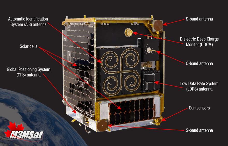
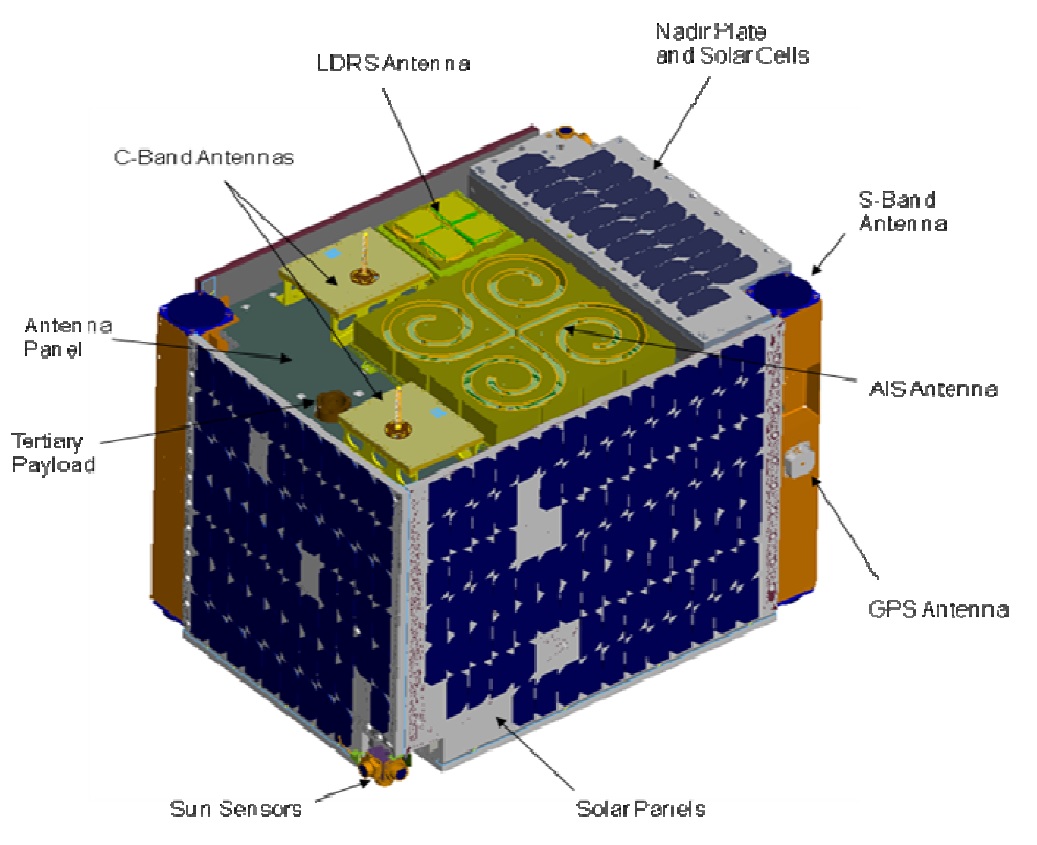
M3MSat is 0.6 by 0.6 by 0.8 meters in size and has a launch mass of approximately 85 Kilograms, hosting an AIS receiver as the primary payload and a Low Data Rate System and Deep-Dielectric Charging Monitor as secondary payloads.
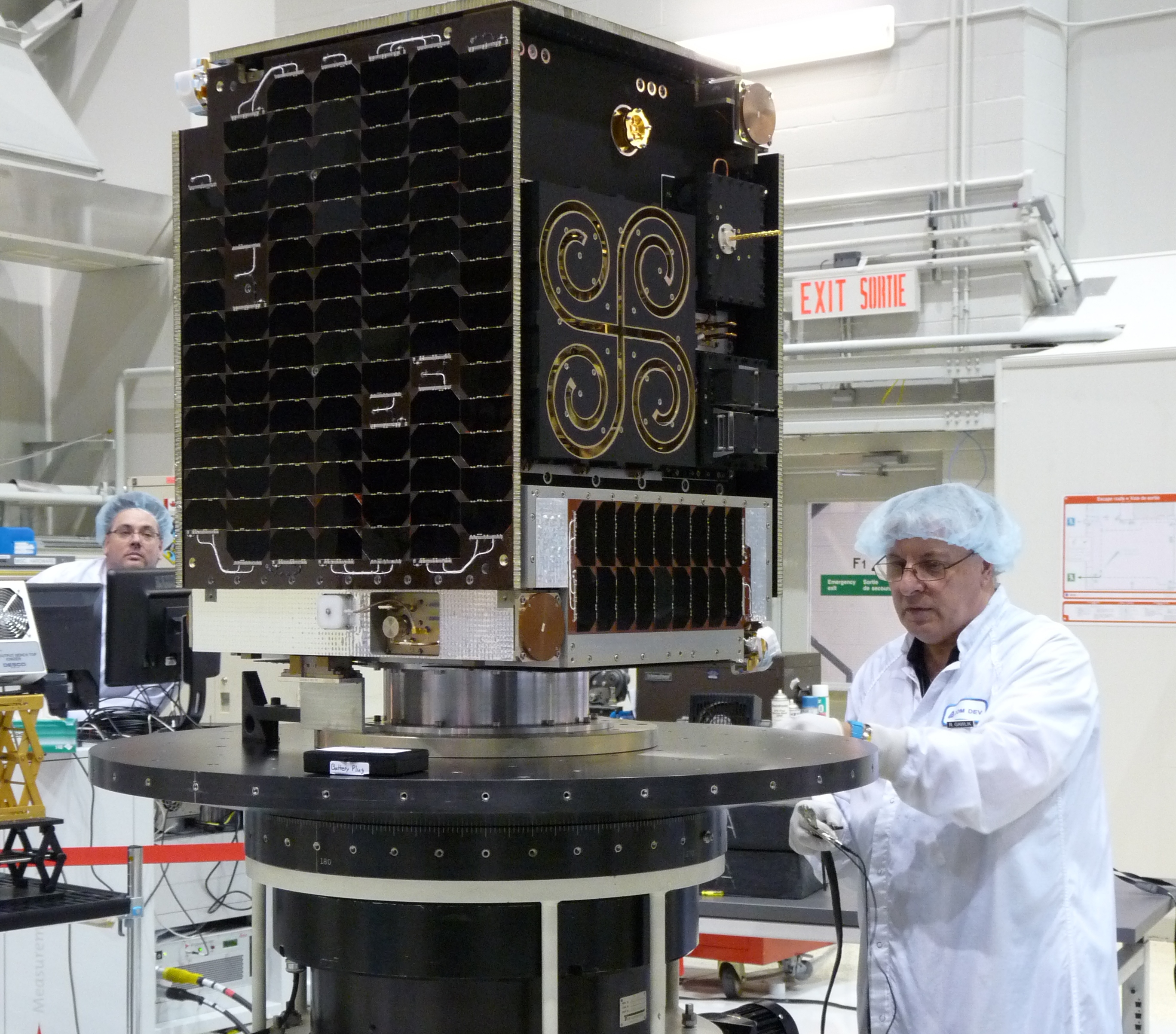
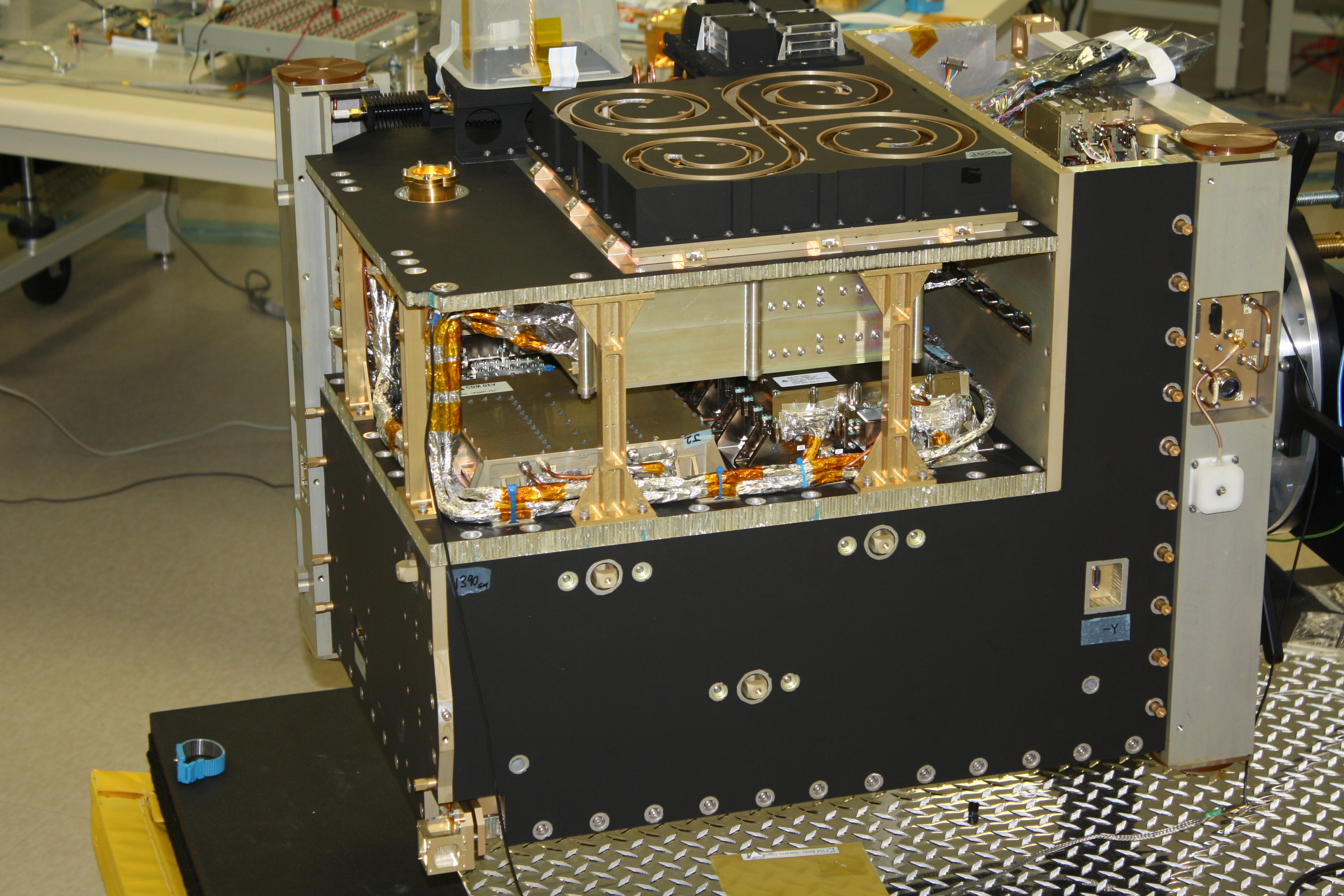
The spacecraft has a modular layout with components of each subsystem placed in a dedicated box featuring common power and CAN (Controller Area Network) Interfaces. The various boxes are then either stacked or installed to the structural panels of the spacecraft, providing easy access to components in case troubleshooting is required during the assembly and testing phase.
The satellite uses body-mounted Triple-Junction Gallium-Arsenide solar cells with 28% efficiency, employing Maximum Power Point Tracking. Six Battery Charge Regulators accept power from the solar panels and regulate the state of charge of a 17.4 Amp-hour Li-Ion battery with three parallel strings of eight cells.
A pair of Power Distribution Units supports 28 switched and 4 unswitched outputs, delivering an average power of 70 Watts of which 15W are allocated for the satellite payload. The unswitched outputs are used by components that are always powered, the receivers, decoders and spacecraft controller, featuring a built-in power-on reset function to clear transient faults via an automatic power cycle.
The Attitude Determination and Control System provides full three-axis control as part of a zero-momentum system, designed to perform nadir pointing at an accuracy better than 5° and agile slews of 180 degrees in less than 15 minutes.
Attitude determination is accomplished with a pair of three-axis magnetometers, 3-axis MEMS rate sensors and six dual-axis sun sensors. Actuation is provided by a set of reaction wheels and magnetic torque rods for wheel unloading. Two strings, each with three orthogonal reaction wheels, are installed on the satellite for redundancy. Each of the wheels has a momentum capacity of 80mNms and generates a maximum torque of 5mNm. The Attitude Determination and Control software runs an Extended Kalman Filter and typical pointing errors are expected to be on the order of 2.5°.

All internal satellite commands and data are carried by a pair of CAN buses, one used as primary and the other in a backup role. Two Onboard Computers are used as 1) a Housekeeping Computer gathering telemetry from the bus and payload systems and completing telecommand execution, and 2) an Attitude Determination and Control Computer is solely responsible for processing inputs from the attitude sensors, executing ADCS algorithms and sending commands to the actuators.
In case of a failure of one computer, their duties will be merged. Both machines have 32-bit microprocessors, 2MB of RAM memory and 2GM of flash storage.
A Centralized Data Storage Unit builds the interface between the satellite and the payload, hosting the in/outputs for payload commanding and telemetry collection, plus power outputs and data connections for high-speed 1.25Mbit/s serial transfer. It also provides the downlink data stream to the satellite’s communications system.
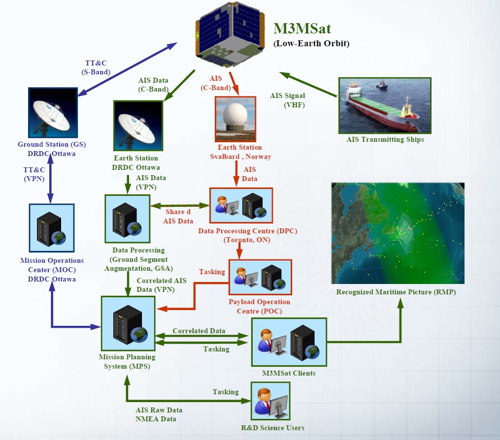
M3MSat relies on S-Band for Telemetry, Tracking and Command functions at rates of 32kbit/s for uplink and 6.25Mbit/s for downlink. An additional C-Band system is part of the satellite’s AIS payload, comprised of two chains that send raw data to the ground at 20Mbit/s.
The primary payload of M3MSat is an Automatic Identification System (AIS) Terminal that can record signals sent by the Automatic Identification System of ships using the VHF frequency. The Automatic Identification System is used by sea vessels that send and receive VHF messages containing identification, position, course and speed information to allow the monitoring of vessel movements and collision avoidance as well as alerting in the event of sudden speed changes.
These signals can be transmitted from ship-to-ship and ship-to-shore to allow the monitoring of a local area, but deploying space-based AIS terminals allows a broad coverage and data relay to ground stations for monitoring of large sea areas. However, due to the large footprint of satellites, overlapping and signal collisions become a problem, especially for frequented traffic routes, requiring a steady improvement in reception technology to separate the different signals.
M3MSat uses two independent AIS chains, though both share the same 30-centimeter diameter VHF antenna that delivers signals to splitters and the two independent VHF receivers. The AIS terminal relies on a Software Defined Radio System, an emerging technology that provides multi-mission capability as the hardware is tuned to each application by means of software optimization. Also, SDR technology allows for simple updates and upgrades of systems through the upload of new operating software.
The Digital Signals Processor is implemented in a Field Programmable Gate Array with a 32-bit microprocessor. Memory provided to the DSP includes 8GB of Flash, 32MB SDRAM, 128KB of PROM. Input data is filtered, down-sampled and processed into digital data which is then stored in the spacecraft memory and condition for re-transmission via C-Band.
Two independent C-Band chains with cross-strapping provide the downlink of AIS data, usually involving the sampled raw spectrum, however, real-time or post-collection message downlink is also possible.
The LDRS – Low Data Rate System secondary payload aims to demonstrate two-way communications at a low data rate for application in the transmission of sensor data, machine-to-machine communications and other packet-based message services. A UHF system is used to collect data from ground-based AIS Base Station terminals and then converted to a C-Band downlink. The UHF signals are down-converted from 400 to 162 MHz and then pushed into the AIS NCAP receiver.
LDRS may find application in the relay of buoy data from the northerly regions of the arctic. These collect temperature in the Arctic ice and deliver relevant aids to navigation. The transmission of the data to users is accomplished with AIS terminals, relying on satellites picking up that data.
DDCM, the Dielectric Deep Charge Monitor, is an experimental payload to monitor the electrical potential of a dielectric sample due to charging in the space environment. This data comes to use in in-orbit flux and material electrical property studies as well as the development of mathematical models of spacecraft charging and space weather.