
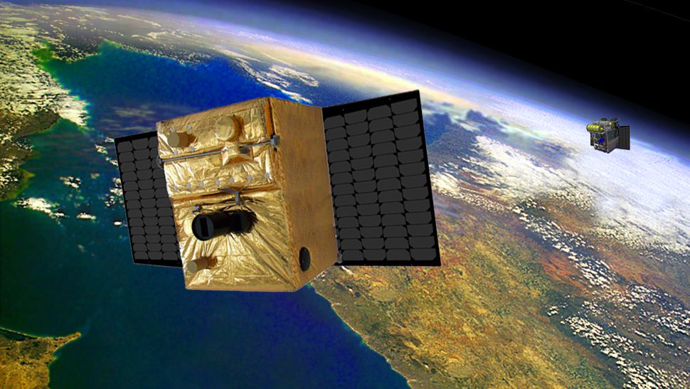
BIROS Satellite

BIROS – the Bispectral Infrared Optical System – is a fire-detection mission operated by the German Aerospace Center to become part of DLR’s FireBird constellation with BIROS operated alongside the TET-1 experimental satellite. The primary goal of the mission is to detect and monitor High Temperature Events which include forest fires, volcanoes and other hot spots.
The BIROS mission includes a number of technology demonstrations and the satellite will eject a 1U CubeSat built at TU Berlin, BEESAT-4.
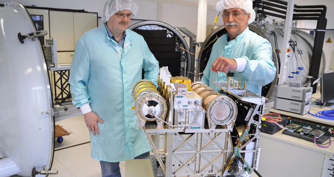
The BIROS satellite employs a slightly improved version of the existing TET-1 satellite bus referred to as TET-X, measuring 67 by 58 by 88 centimeters in size when in its stowed launch configuration. The bus weighs 70 Kilograms and offers a 46 by 46 by 43cm payload volume, accommodating payloads of up to 50 Kilograms to create a spacecraft mass of 130 Kilograms.
The TET-X satellite bus comprises three major segments – the Service Module, the Electronics Segment and the Payload Module.

The satellite features three solar panels, one fixed to the sun-pointing body panel and two deployable panels to create a total solar panel size of 1.54 by 0.88 meters. End of Life power is expected to be 280 Watts, fed to a Power Control and Distribution Unit that controls the state of charge of a 520 Watt-hour Li-Ion battery and conditions the satellite’s power bus, distributing power to all bus and payload loads.
Attitude Determination is accomplished with a pair of Star Trackers, two Inertial Measurement Units, and two sets of Coarse Sun Sensors while four reaction wheels and redundant magnetic torque rods are responsible for attitude actuation. Two GPS receivers are used for orbit and position determination as well as time synchronization. A Configuration Management System is in charge of operating the redundancies of the ADCS hardware, providing autonomous failure detection and diagnosis.
BIROS achieves a pointing knowledge of around 10 arcsec and a pointing accuracy of 2 arcmin with low jitter. The GPS system delivers a position knowledge of 10 meters that is improved to 1 meters through ground data processing.
All components of the Electronic Segment are facilitated on 16 by 10cm Printed Circuit Boards with a maximum of 30 boards for the satellite platform and payload electronics. The Onboard Computer in charge of all satellite functions is a triple-redundant design with additional watchdog circuits for failure detection. Typically, one OBC is in a worker mode, controlling the satellite’s functions while another monitors the operation of the worker.
Communications with the ground are handled in S-Band with two redundant receivers operating at a 4kbit/s uplink data rate and redundant transmitters sending data to the ground at 6Mbit/s. BIROS also hosts a VHF terminal through which it will communicate with the ORBCOMM Machine-to-Machine satellite communications system in an orbit of 750 Kilometers. This system is used to inform satellite operators of any detected hot spots with short latency between detection and downlink of data.

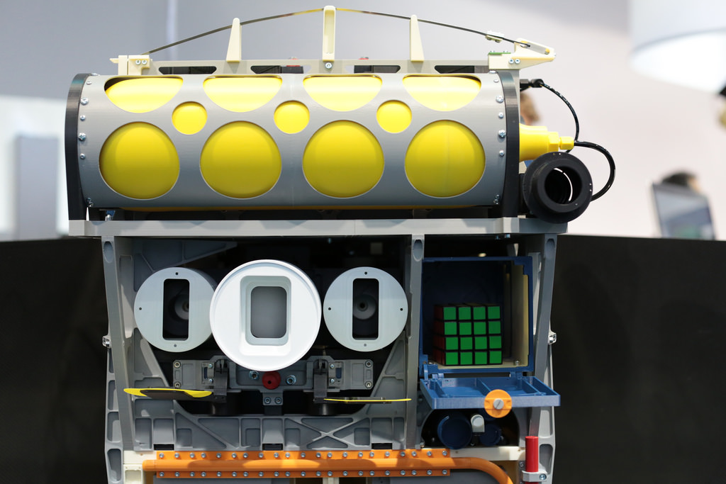
BIROS hosts a MicroJet Propulsion System for orbital maneuvers. The system uses a high-pressure nitrogen tank at 310 bar feeding gas through Flow Control Units to a number of Thruster Units capable of operating in ResistoJet mode employing heated elements to generate 67 Millinewtons of thrust per thruster, or in Cold Gas Mode in which the thrusters deliver 118mN of thrust. The entire MicroJet 2000 assembly, containing two independent tank, controller and thruster strings for redundancy, is 55 by 49 by 18 centimeters in size and weighs 21 Kilograms, occupying the upper deck of the spacecraft.

The primary payload of the satellite is the Optical IR Instrument, designed and developed by the German Aerospace Center. It includes two infrared imagers and a single imaging system covering the visible and near infrared range. The system’s overall objective is to detect and quantify High Temperature Events such as wildfires or volcanoes.
Tasks completed by the payload include the detection of hotspots, geo-referencing of fire fronts, temperature determination and direct transmission of data to users on the ground as time is of the essence when making decisions to suppress fires and mobilize crews.
All three cameras of the Optical IR Instruments are employed as pushbroom sensors, sweeping out an image swath as the satellite moves in its orbital path.
The Visible Near-Infrared Camera (VNIR) has a focal length of 90.6 millimeters and a 19.6-degree field of view. In its focal plane lies a Charged Coupled Device with three sections, each with 5164 pixels, outfitted with the following bandpass filters: 460-560nm (green), 565-725 (red) and 790-930 (Near Infrared). The CCD detector comprises 7µm pixels and a passive cooling mechanism to maintain a temperature of 20°C.
The VNIR Camera covers a 211-Kilometer swath with a ground resolution of 42.4 meters. The raw data rate from the instrument peaks at 44Mbit/s.
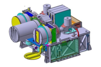

The two Bi-Spectral Cameras cover the Mid-Wave and Long-Wave Infrared ranges of 3.4 – 4.2 µm and 8.5 – 9.3 µm. Both cameras have a 19-degree field of view and a focal length of 46.4 millimeters, featuring Cadmium-Mercury-Telluride detector arrays cooled to an operational temperature of 80 to 100K using a Stirling cooler. Each detector array consists of 2 x 512 pixels, 30 µm x 30 µm in size.
The Bi-Spectral cameras cover a 178-Kilometer ground swath with a pixel resolution of 356 meters. Typically, the system operates at a 350kbit/s data rate.
A technical demonstration payload hosted by BIROS is OSIRIS, the Optical Space Infrared Downlink System, an optical communications system enabling high-speed data links up to 10 Gbit/s for small satellite missions.
Typically, satellites of small size are restricted to use S- or X-Band with available data rates maxing out at a few hundred Mbit/s on X-Band and only a few Mbit/s on S-Band.
The OSIRIS payload carries two separate laser sources with an Intensity Modulation/Direct Detection scheme operating at a 1550-nanometer wavelength in the infrared band. The system has been designed to operate at 1Gbit/s with laser beam pointing accomplished through steering the attitude of the entire satellite – a simpler approach with the advantage of less complexity and weight, but the drawback of having to interrupt satellite operations for optical downlink. A beacon laser acts as a tracking sensor to help the satellite properly track the ground station as it goes overhead.
OSIRIS is comprised of three major components, the laser sources, a power supply module and the Optical Bench which hosts the Tracking Sensor and two collimators to be able to deliver two different laser signals at different divergence angles.
The Tracking Sensor’s main element is a quadrant-type Indium-Gallium-Arsenide PIN diode with a 1-millimeter diameter residing in the focal plane of a telescope mounted parallel to the laser collimators to receive illumination from the ground-based beacon laser.
The signal is modulated with tracking data up to 1Mbit/s as well as a 10kHz rectangular signal. 70 Picowatts of input power per quadrant are necessary for optical tracking of the incoming beam direction.
The collimators, also residing on the aluminum optical bench, have different beam divergences of 1200µrad and 200µrad. The collimator with the larger divergence is used when the satellite has to rely on data from its attitude sensors to track the ground station while the 200µrad collimator comes into play when the tracking sensor is steering the satellite orientation relative to the ground station. Alignment between all three optical elements is better than 30 µrad.
OSIRIS has a mass of 5 Kilograms and measures 25 x 20 x 10 centimeters in size with a maximum power draw of 50 Watts.
Another experimental payload hosted by BIROS is AVANTI – the Autonomous Vision Approach Navigation and Target Identification – to demonstrate navigation systems for future On-Orbit Servicing applications capable of approach, identification, and rendezvous with a non-cooperative, passive spacecraft from large distances over 10 Kilometers.
AVANTI demonstrates a vision-based non-cooperative autonomous rendezvous system using a camera head of the star tracker of BIROS to complete navigation at distances of ten Kilometers to a few hundred meters to the BEESAT-4 Picosatellite ejected from a spring-loaded deployer on BIROS. The system purely relies on angular measurements to determine the relative geometry between the satellites and ground-based tracking is employed to monitor the moves of the active spacecraft.
BEESAT-4

The BEESAT-4 mission involves a 1U CubeSat built at TU Berlin, ejected from a spring-loaded deployer on the BIROS satellite. The 10 x 10 x 10-centimeter satellite is outfitted with an advanced miniaturized GPS receiver for testing in orbit.
The satellite furthermore acts as a navigation target for the AVANTI demonstration on the BIROS mission, aiming for BEESAT-4 to act as passive non-cooperating spacecraft that the active satellite can rendezvous with using an advanced software processing optical navigation data.
The Phoenix GPS Receiver will collect data to demonstrate precise position and orbit determination. Also, the satellite hosts a camera for the collection of Earth imagery. BEESAT-4 makes use of a three-axis stabilization system employing reaction wheels and magnetic torquers.