
AstroSat – Astronomy Satellite of India
AstroSat, known in full as Astronomy Satellite of India, is the country’s first dedicated astronomy mission classed as a national space observatory. The AstroSat spacecraft will enable Indian scientists to conduct cutting edge research in a number of astronomical fields using the different instruments of the satellite that will operate from a Low Earth Orbit. AstroSat carries a range of payloads to conduct X-Ray and Ultraviolet astronomy in order to help address some of the outstanding questions in modern day astrophysics.
The mission has a number of scientific goals, the primary mission objective being the observation of targets in multiple wavelengths using the spacecraft’s five co-aligned telescopes covering the hard X-rays through the ultraviolet range of the spectrum into the visible wavelengths. The observations will particularly focus on Active Galactic Nuclei, binary stars, flaring stars, star clusters and more. X-ray observations will be made across a broad energy band with high resolution using three co-aligned instruments. Time-resolution achieved by the AstroSat instruments will allow for the study of periodic, aperiodic and chaotic X-ray binaries and their pulse and orbital periods. Furthermore, AstroSat will deliver UV data for morphological studies of a number of targets to deliver additional spectral information.
AstroSat is the product of a collaboration between several Indian and foreign institutions. Foreign partners contributing to the project are the Canadian Space Agency and Leicester University in the United Kingdom.
AstroSat has a liftoff mass of 1,513 Kilograms and is based on the IRS-1 satellite bus. IRS stands for Indian Remote Sensing satellite bus and first flew in 1988 when the first prototype satellite was delivered to orbit by a Vostok rocket. Over the years, the systems of the IRS bus were improved and went through a series of generations to keep the satellite a state of the art system. IRS has been primarily used for Earth Observation missions including cartography, ocean monitoring and imaging satellites to deliver data by looking back at Earth. AstroSat will be the first dedicated use of IRS-1 to look away from Earth and peer into deep space.
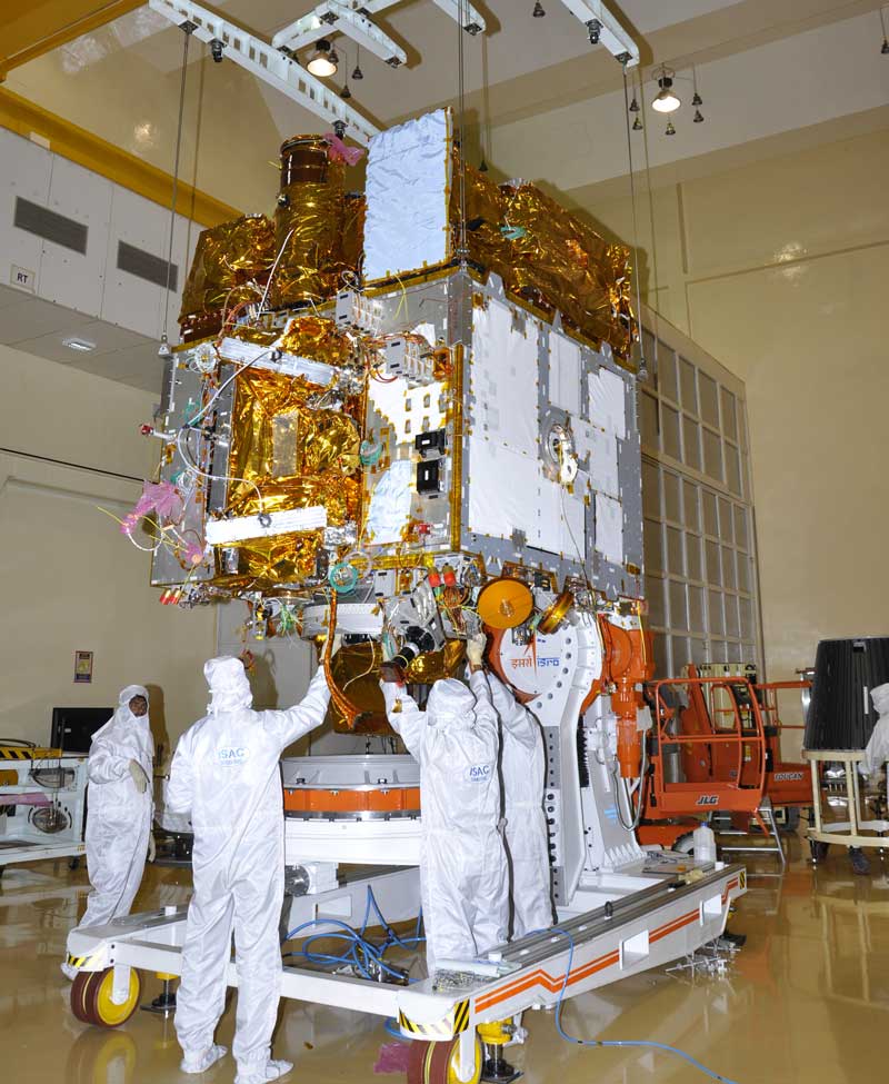
The AstroSat spacecraft consists of two major components – the Bus Management Unit and the Instrument Unit. The Bus Management Unit hosts all satellite support systems and is similar to that used on the CartoSat-2 spacecraft launched in 2007. Overall, the satellite measures 1.69 by 1.75 by 1.30 meters in size when in its stowed launch configuration.
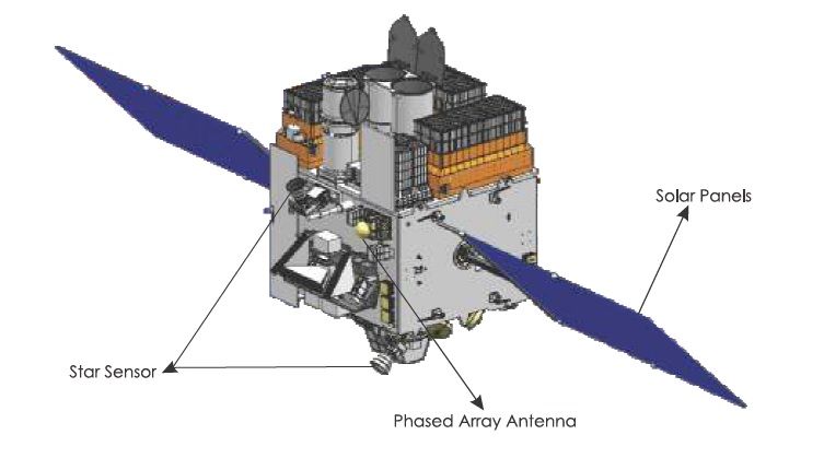
Two deployable solar arrays, each with two panels, are covered with Triple-Junction Gallium Arsenide Solar Cells that deliver 2,100 Watts of power. The solar arrays employ single-axis rotation to track the sun using data delivered by sun sensors through which the solar vector is calculated. Electrical power is stored in two Lithium-ion batteries, each with a capacity of 36 Amp-hours.
Attitude Determination is accomplished by two Star Trackers and three highly stable gyroscopes. The Star Trackers are imagers that capture frames of the star-filled sky that are then put through a processing algorithm which compares the acquired frame with thousands of known bright stars to accurately determine the spacecraft’s three-axis orientation in space. The gyros are used to precisely track the satellite body rates and help with attitude determination and rate dampening so that the Star Trackers can begin acquiring frames.

Attitude Actuation is accomplished through the use of high-torque reaction wheels coupled with magnetic torquers that make use of Earth’s magnetic field to counter the forces imparted by the reaction wheels when they are spun down as part of regular momentum dumps. Overall, the satellite achieves a pointing accuracy better than 0.05 degrees on all three axes with a high stability as drift rates reach at most 0.2arcsec per second – a requirement for the precise observations AstroSat sets out to complete.
The AstroSat spacecraft features a liquid-fueled propulsion system consisting of eight 11-Newton thrusters fed from a central Hydrazine tank launching with a propellant mass of 43 Kilograms. The thrusters will be used to assist in attitude control when required and provide orbit adjustments and maintenance over the five-year mission duration.
The AstroSat spacecraft has to handle a large volume of data delivered by its five science instruments and therefore uses a high-speed onboard data system that transfers and processes payload data to a 160Gbit Solid State Recorder where data is kept until being downlinked to the ground as part of several downlink sessions per day. The average payload data rate during instrument operation is 105Mbit/s. AstroSat is outfitted with a high-speed X-Band terminal that reaches data downlink data rates of 210Mbit/s for the transmission of recorded data. Satellite telemetry downlink and command uplink is accomplished via S-Band.
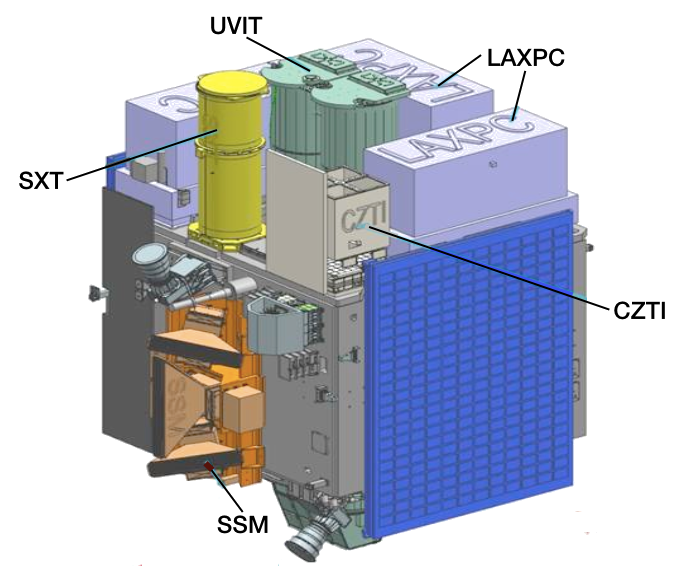
Astro Sat hosts a total of five instruments:
– Ultraviolet Imaging Telescope (UVIT)
– Soft X-Ray Imaging Telescope (SXT)
– Large Area Xenon Proportional Counter (LAXPC)
– Cadmium-Zinc-Telluride Coded Mask Imager (CZTI)
– Scanning Sky Monitor (SSM)
– Charged Particle Monitor (CPM)
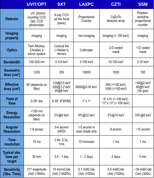
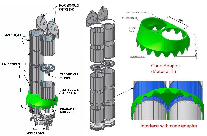
Ultraviolet Imaging Telescope
AstroSat’s Ultraviolet Imaging Telescope UVIT is a collaboration between the Indian Space Research Organization and the Canadian Space Agency reaching back as far as 2004 when the initial contract was signed, calling for Canada providing scientific expertise, funding for the instrument and the UV photon counter.
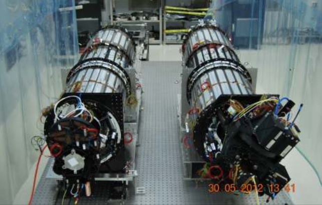
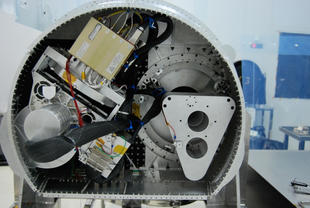
The UVIT instrument weighs 230 Kilograms and draws a maximum power of 117 Watts. The telescopes, given their requirement of a stable thermal environment, are mounted separately from the main electronics box of the instrument that resides on the satellite deck, connected via a cable harness. The telescope assembly weighs around 202kg, the electronics 28kg.
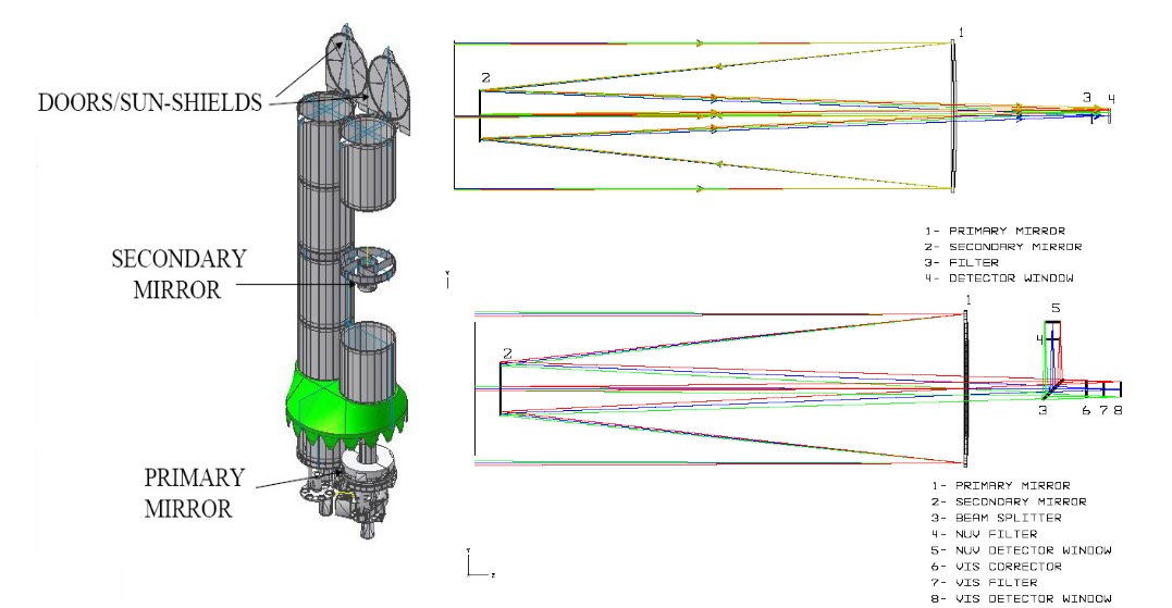
UVIT covers three channels spanning across the Far-UV spectrum (130-180 nanometers), the Near-UV (180-300nm) and a part of the Visible Spectrum (320-530nm). To facilitate the acquisition of imagery of this broad section of the high-energy part of the spectrum, UVIT uses two co-aligned telescopes, one for the Far-UV wavelengths and the other for the NUV and VIS observations. The optics of the telescopes are identical, making use of a Ritchey-Chretien arrangement consisting of a specialized Cassegrain Telescope using a hyperbolic primary mirror and a hyperbolic secondary mirror to eliminate third-order coma and spherical aberration. RCT designs are well-suited for wide-field and photographic observations with good off-axis performance at a large field of view free of optical errors.
The primary mirror of the telescope is 37.5 centimeters in diameter and the optics create a focal length of 4.75 meters, covering a 28-arcmin field of view at an angular resolution between 1.8 and 2.0 arcsec depending on the wavelength. The primary mirror consists of highly stable Zerodur and has a 155-millimeter central hole while the secondary mirror also uses Zerodur and is 14-centimeters in diameter. Both mirrors achieve a reflectivity of higher than 60%.
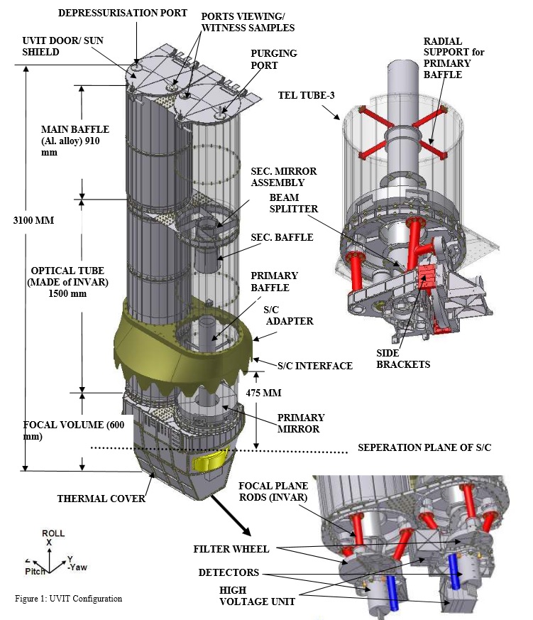
The UVIT instrument uses a main baffle made of aluminum alloy for stray light rejection. The telescope tube is made of INVAR (nickel-iron) given its high thermal stability which also makes it suitable for the structural assembly holding in place the optical components and detector systems. The main tube of the telescope consists of three sections and is responsible to maintain the separation between the primary and secondary mirrors. Three INVAR rods are glued to the mirror assembly and structurally attach it to a ring affixed to the optical bench.
The entrance opening of the two UVIT telescope assemblies is covered by a moving sun shield that protects the optics from direct exposure to sunlight and also protects the internal telescope components from contamination by combustion products. When in operation, UVIT is kept at a sun avoidance angle of 45°.
Thermal control on the UVIT instrument is provided by Multi-Layer Insulation in which the entire telescope assembly is covered. Heaters are used to keep the instrument at a constant temperature when in a cold environment with heater control accomplished in a closed loop control. In warm environments, an Optical Solar Reflector is used to reject excess heat and keep the system within its operational temperature range of 18 to 22°C. Thermal control has to account for internal loads such as heat dissipation by the filter wheel motors and detector electronics while external thermal loads arise from solar illumination, Earthshine and albedo of the Earth.
In the optical path of each telescope is a filter wheel for the selection of the appropriate wavelength throughput band. The wheels include blind blocks for calibration of the detectors as well as gratings that can be used for the two ultraviolet channels to conduct slit-less spectroscopy to add to the instrument’s science data output. The filter wheel in the NUV channel has 6 filters, a grating and a block while the VIS channel sports 5 filters and a block.
The detectors of the UVIT instrument are photon counting imagers featuring CMOS detectors coupled with Microchannel Plate Detectors.
UVIT can operate in two different imaging modes, high gain photon counting mode in which individual photons are detected as they impact the detectors, and low gain integration mode in which individual photons can not be distinguished. The high gain mode is typically used by the UV channels where the flux is relatively low while the VIS channel has a high photon flux and normally uses the low gain mode.
Given the limitations in attitude control accuracy on the satellite and anticipated drift rates, the UVIT instrument has to implement corrective measures, especially for longer integrations on an observation target. In its nominal operation mode, the instrument acquires between 30 and 200 UV images per second while the VIS channel collects one image a second. The VIS images are then used in a shift and add algorithm as part of ground processing during which UV images are combined after attitude drifts are corrected for. This enables longer UV integrations which are required to collect sufficient photons for UV imaging.
Soft X-Ray Imaging Telescope
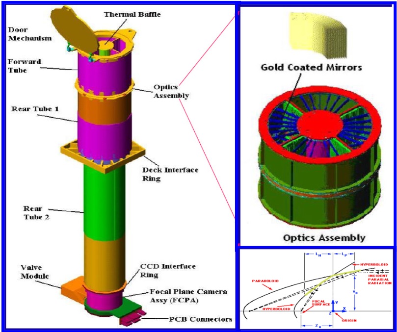
To cover a second high-energy area of the electromagnetic spectrum, AstroSat hosts a series of X-ray sensors, the SXT instrument at the forefront to capture x-ray imagery in the 0.3 to 8 kilo-Electronvolt range. The SXT telescope assembly is 2.47 meters long, consisting of a multi-segment Carbon-Fiber Reinforced Polymer tube with a top lid cover on the entrance end in addition to a thermal baffle.
To capture X-rays at the desired energy levels, SXT uses a Wolter I telescope design that uses only grazing incidence optics because the conventional telescopes employing lenses or mirrors are of no use for X-rays – transparent lenses have a refractive index substantially different than one whereas X-rays require refractive indices very close to one, and mirrors, when used at near-normal incident angles, will not reflect the x-rays, instead transmitting or absorbing them which is of no use when trying to focus X-rays onto a detector.
Therefore, X-ray optics are only useful if the angle from the plane of reflection is very low, typically below 2 degrees. These grazing incidence mirror arrangements were first outlined by Hans Wolter in the 1950s with the Type I design being the most frequently used option in modern space-based X-ray observatories.
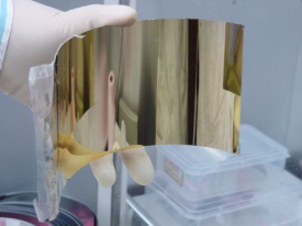
SXT features 41 concentric shells building the grazing optics, each coated with a gold layer, focusing X-rays onto the detector from a field of view of 41 by 41 arcmin. The optics create a total focal length of 2.0 meters.
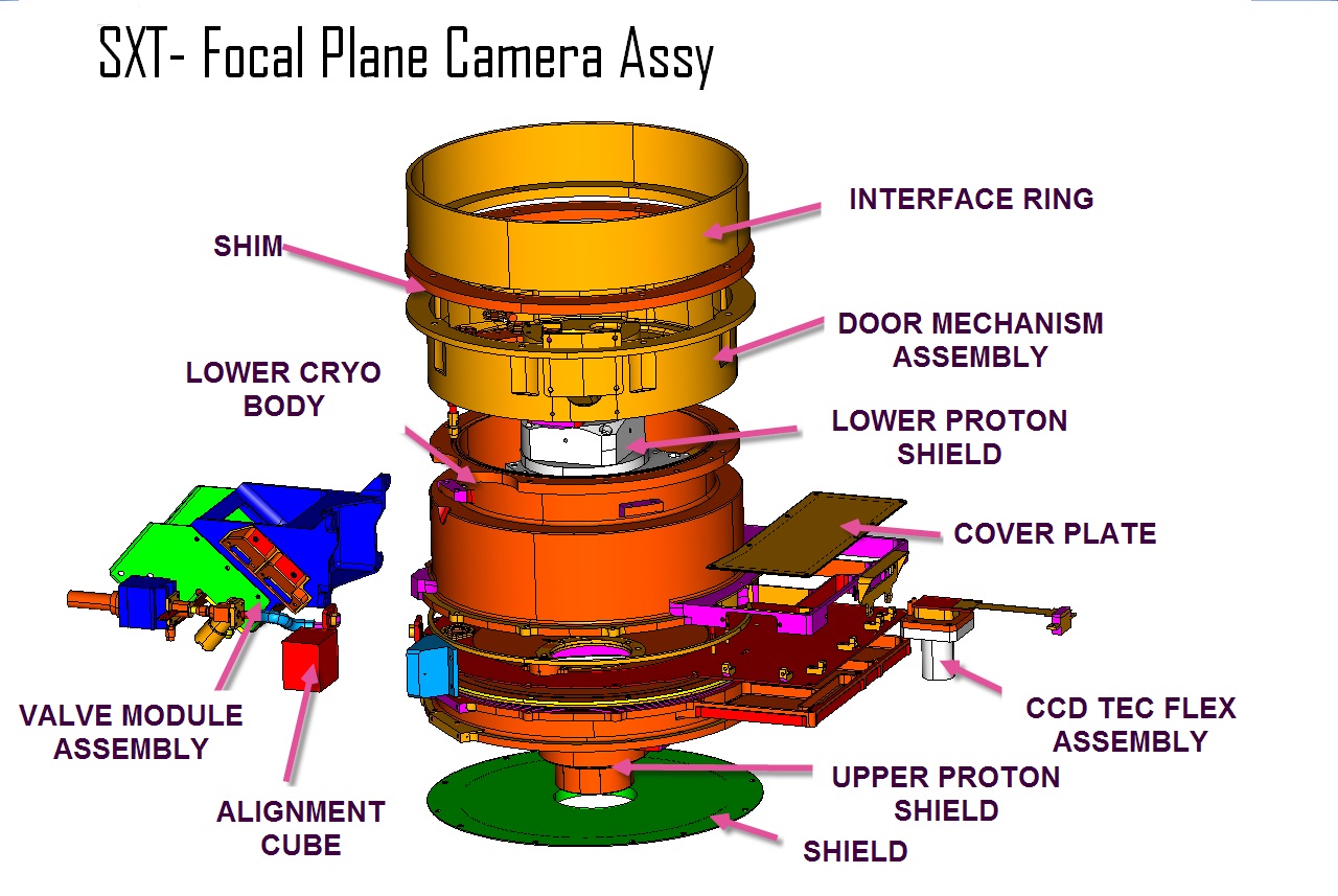
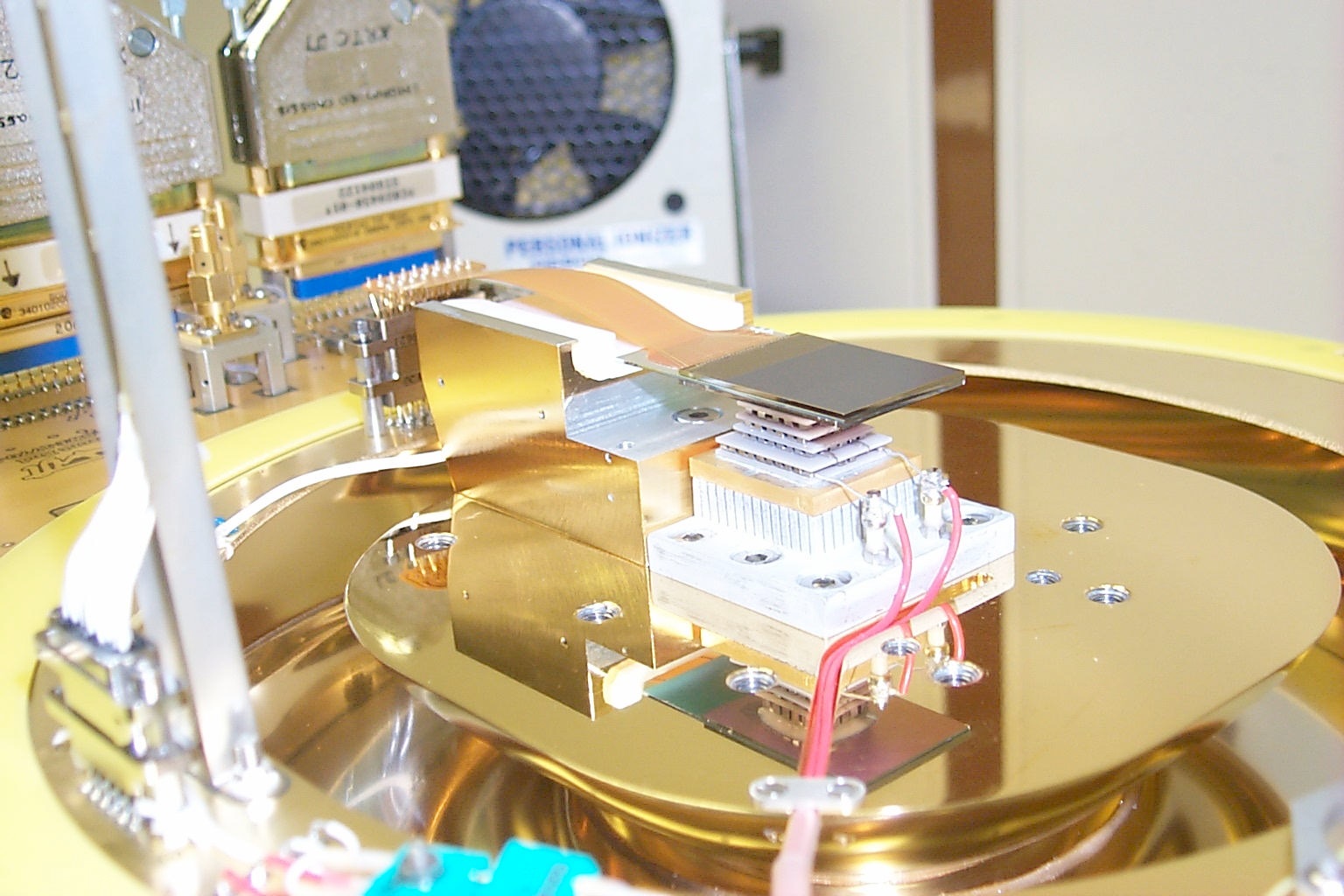
SXT uses a Charged Coupled Device detector supplied by e2V. The 600 by 600-pixel detector is cooled to -80°C through a thermoelectric cooling system to limit noise. Each pixel is 40 by 40 microns in size and is read out using a frame transfer system to allow the system to operate at a rapid cadence.
The detector is only operated in single photon counting mode so that the energy of each X-ray photon can be measured as a function of the number of liberated electron-hole pairs. This allows for the creation of detailed X-ray spectra across the image.
Protons are rejected by an aluminum shield to avoid damage to the detector when the satellite encounters an increased proton flux. Furthermore, the instrument includes Fe55 calibration sources and a block filter consisting of an 48.8-nanometer aluminum layer and 184 nanometers of polyamide film on the outside.
Large Area Xenon Proportional Counters (LAXPC)
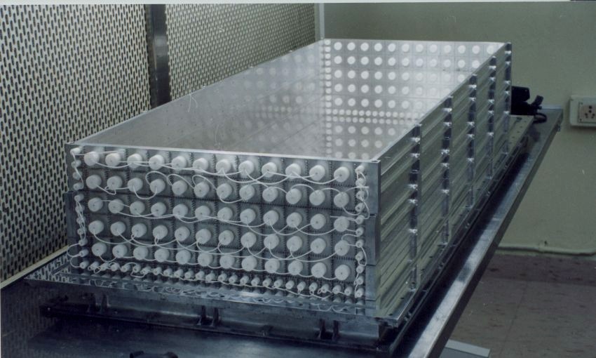
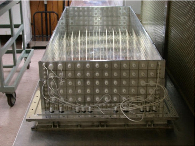
The AstroSat spacecraft is equipped with three identical Large-Area Xenon Proportional Counters dedicated to the measurement of x-rays across a wide energy range for low-resolution studies. LAXPC sets out to measure x-Rays at energies from 3 to 80 keV with a high detection efficiency across the energy band at a small internal background. The field of view of each LAXPC is about 1 by 1 degree so that source confusion is minimized and coordinated observations with the SXT instrument are possible.
The detectors consist of a chamber that is 15 centimeters deep and filled with a Xenon-based gas mixture at a pressure of 2 bar. The top panel of each detector consists of a 50-micrometer aluminized mylar window to ensure X-ray photons with energies greater than 2-3 keV are transmitted and can enter the chamber where they can collide with the inert Xenon atoms, in the process creating a series of ion-electron pairs. The number of generated ions and electrons depends on the energy of the incoming photon.
Once ions and electrons are present, they begin to drift towards the cathode and anode, respectively. In the anode region, the field strength becomes strong enough to generate Townsend discharges in which the acceleration of the free electrons in the electric field give rise to electrical conduction in a gas through avalanche multiplication generated by the impacts of electrons and gas molecules. This multiplication effect is used as a built-in amplification process to generate a signal strong enough for detection. The total ion current that is measured is proportional to the energy of the incident photon, provided only one avalanche event is generated. Careful setup of the chamber dimensions, electrode size and voltage coupled with extensive ground calibration ensures a proportional operation of the system across its specified energy range.
LAXPC features a honeycomb shaped collimator that supports the mylar entrance in order to generate a 5 x 5° field of view while a set of mechanical collimators further reduces the field of view to 1 x 1°. The mechanical collimators consist of tin, copper and aluminum in co-alignment with the window support collimator.
In each Wired Anode Assembly, there are 60 anode cells arranged in five rows of 13. The anodes themselves are 37-micron diameter gold-plated wires. The detection efficiency of the system approaches 100% for photons at energies under 50 keV and is still around 50% for photons at 80 keV.
Because of the sensitivity of this measurement method, LAXPC includes a gas purification system that is used periodically to remove any oxygen and water from the mixture to prevent a degradation in energy resolution due to outgassing of the detector walls.
The instrument can support variable integration times for many energy channels, generate pulse height historgrams with variable integration time, time tag each photon event with 10-microsecond accuracy and operate in a fast-counting mode in case of X-ray bursts.
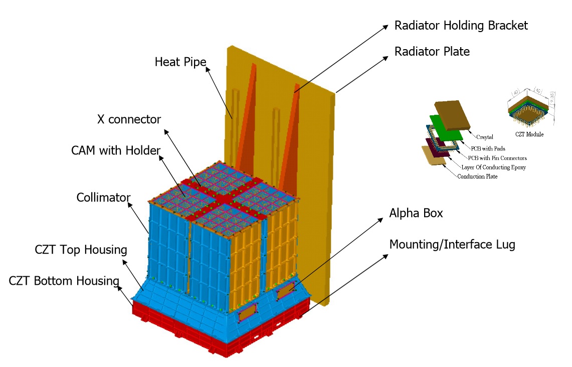
Cadmium-Zinc-Telluride Coded Mask Imager (CZTI)
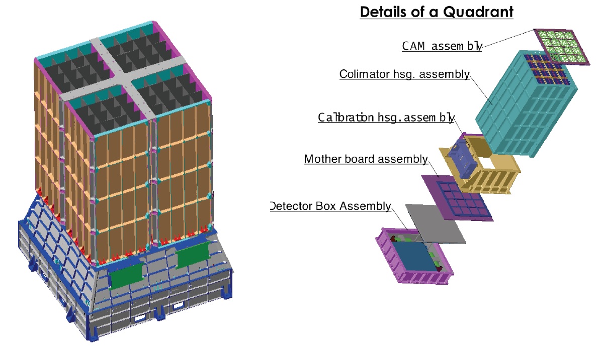
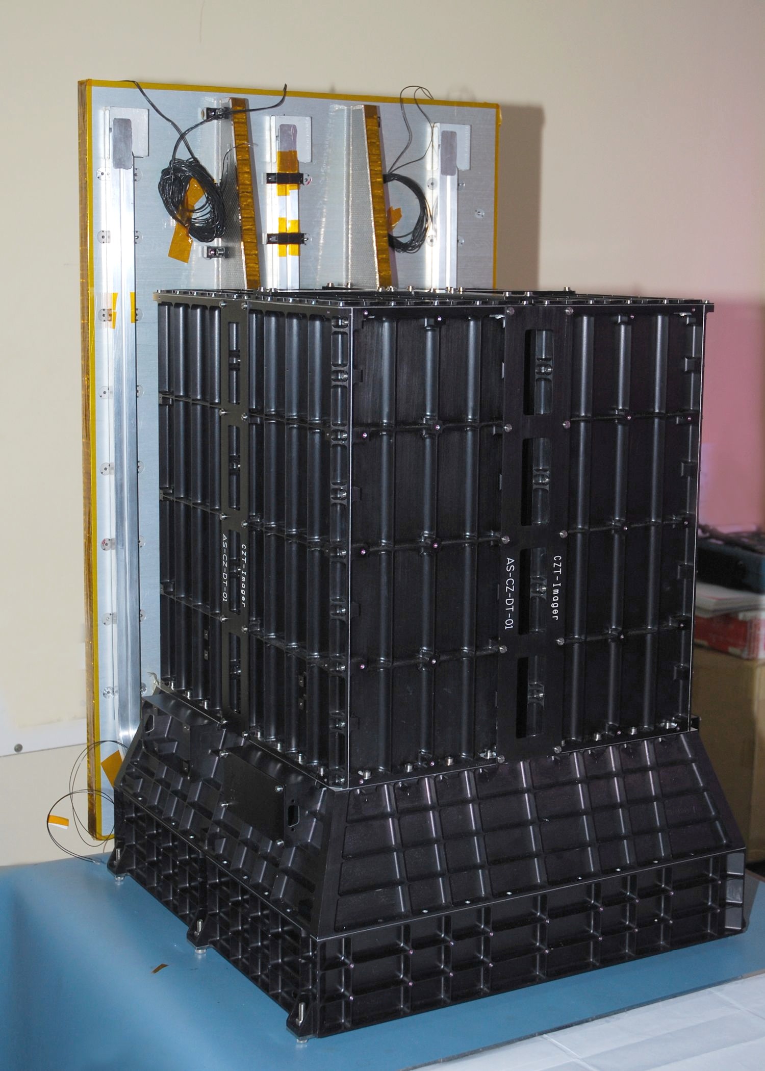
CZTI is hosted by AstroSat as a hard X-ray monitor with limited imaging capability. The 50-Kilogram instrument consists primarily of a pixelated Cadmium-Zinc-Telluride detector array which can cover an X-ray energy range of 10 to 150 keV for imaging and energies up to 1 MeV for photometric analysis.
The CdZnTe detectors deliver an excellent detection efficiency of nearly 100% at 100 keV and a equally excellent image resolution of 2% at 60 keV. The small pixels used on the detector also permit medium resolution imaging of hard X-ray sources. Imaging is accomplished by placing a pinhole mask over the detector array so that the shift in the shadow pattern can be put through a deconvolution procedure to encode the location of the X-ray source in the sky.
The detector assembly consists of four identical quadrants, each is independent and hosts 64 x 64 detectors (for a total of 16,384 pixels), though the mask pattern of adjacent quadrant is rotated by 90 degrees. Each pixel is 2.4 by 2.4 millimeters in size with a thickness of 5mm. The pixel read-out of the detector is accomplished with 128 Application Specific Integrated Circuits.
The instrument field of view is 6 x 6 degrees for imaging at 10 to 100 keV and 17 x 17° when defined by the mask housing in case energies exceed 100 keV. A veto layer of 2-centimeter thick Caesium-Iodine coupled to a photo multiplier diode is used to separate photons entering the instrument from outside the field of view. Instrument thermal control is provided by a radiator.
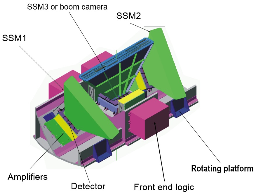
Scanning Sky Monitor (SSM)
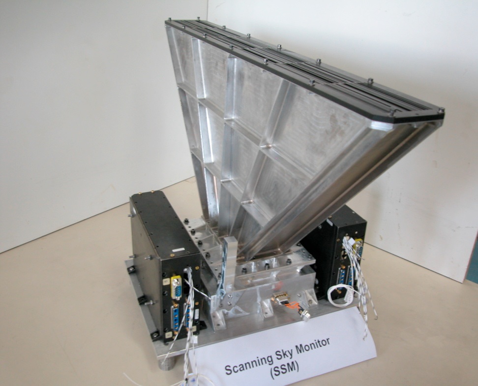
The Scanning Sky Monitor is a wide-field-of-view X-ray monitoring instrument that detects, locates and monitors x-ray transient events, completes several observations of known bright X-ray sources per day, and delivers alerts to other instruments of ongoing X-ray events.
SSM is comprised of three position sensitive proportional counters that use the same detection technique as the LAXPC instrument. Resistive wires are used as anodes and the output charge measured on either end of the wire provides the position of the X-ray interaction within the detector chamber, thus creating an imaging plane within the detector. A coded mask featuring a series of slits generates shadows on the detector from which the sky brightness distribution can be calculated in onboard and ground processing.
The three sensor assemblies sit on a rotating platform with one sensor aligned with the axis of rotation and the other two are arranged so that the instrument field of view forms a figure X. The instantaneous field of view of the three sensors is 10 by 90° so that a stepwise rotation of 10-degrees at a time can deliver a hemispherical image of the sky with an integration time of 10 minutes at each location.
SSM covers an energy range of 2 to 10 keV at an angular resolution of 10 arcmin and a time resolution of 1 millisecond.
Charged Particle Monitor (CPM)
The Charged Particle Monitor is not considered part of the science payload of AstroSat, but provides an important auxiliary function in the detection of charged particles in the direct vicinity of the satellite. AstroSat operates from an 8-degree inclination orbit which places it outside the South Atlantic Anomaly for the majority of its orbits, though about one third of orbits traverse the SAA. The high proton and electron flux in this area can lead to damage to the high-voltage systems, the detectors and proportion counters. CPM is employed as an onboard safeguard system that triggers the deactivation of all instruments that could be harmed by high-energy particles.
CPM consists of a Scintillator coupled with a Photomultiplier Tube. The energy of incoming electrons and protons striking the scintillator is converted to photons. The light pulses are then detected by the Photomultiplier and generate an electrical pulse which is then routed though a Charge Sensitive Pre-Amplifier. A Lower Level Discriminator monitors the signals with respect to a programmed threshold that would trigger the shutdown of all systems that need to be protected.
The scintillator is a small 1 by 1 by 1 centimeter Caesium Iodine crystal capturing particles at energies of over 1.2MeV. CPM weighs around 2 Kilograms and is 18 by 15 by 5 centimeters in size – a lightweight addition that can extend the satellite’s overall lifetime by protecting essential instrument systems.