
Disturbance Reduction System DRS

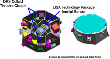
The Disturbance Reduction System is the NASA’s instrument package of the LISA Pathfinder, developed at the Jet Propulsion Laboratory. It consists of a Drag-Free Attitude Control System, micro-Newton (µN) colloidal thrusters and associated control equipment. DRS uses the LISA Technology Package inertial sensors as its drag-free sensors to control the spacecraft attitude with independent drag-free software and actuators than the Cold Gas Micropropulsion System. This means that the Cold Gas Thrusters and DRS have to be operated separately during allocated operation periods.
The goal of DRS is to maintain the position of the spacecraft with respect to the test mass of LTP to within 10 nm √Hz over an operational frequency range of 1-30 mHz. DRS controls the spacecraft position with respect to proof mass one and minimizes disturbances on the second mass without taking into account its actual position.
In principle, DRS uses the electrodes inside the test mass housings to measure the position and orientation of the proof masses using a capacitive sensing system while a laser interferometer measures the distance changes between the masses to infer acceleration noise that is to be corrected by the Disturbance Reduction System. Based on the measurements, colloidal microthrusters are used to counteract the external forces which arise primarily due to solar pressure acting on the spacecraft. The thrust level is continuously adjusted to keep the spacecraft centered around the test masses in their free-fall environment.
DRS hosts Colloid Micro-Newton Thruster Assemblies (CMNTAs) that smoothly and continuously counter any external disturbances, controlling all six degrees of freedom of spacecraft motion. CMNTA supports an operational thrust range of 5 to 30 Micro-Newtons with a resolution exceeding 0.1 µN and a specific impulse of up to 275 seconds.
The Colloid Thrusters belong to the Electrostatic Ion Propulsion family in which high voltages are used to generate electrostatic fields capable of accelerating positively charged ions to large exhaust velocities and so generate thrust components.
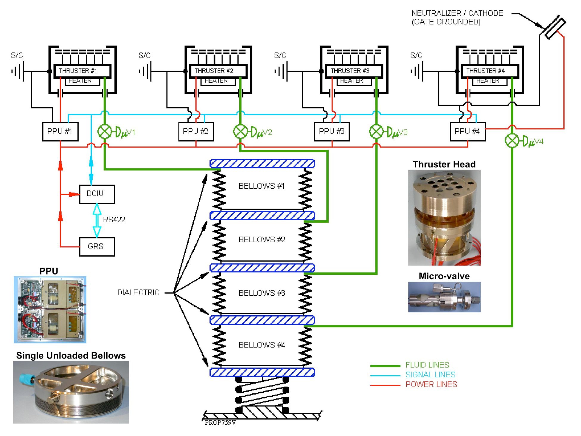
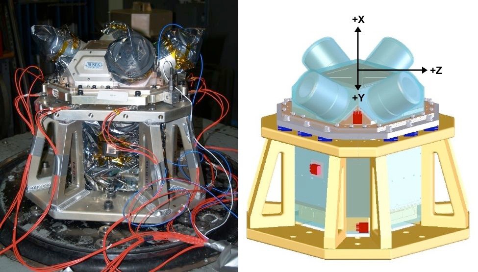
The CMNTA thrusters feed colloidal fluid propellant through a needle by using pressure. At the tip of the needle, a high electric field its supplied to form small droplets which are then ejected from the tip. This electrospray is spontaneously charged and accelerated in the electric field. With one needle, a thrust of up to 3µN can be achieved. Nine individually controllable needles are part of each thruster. Four thrusters are installed on each assembly to be able to deliver thrust components in all directions. Two DRS thrusters assemblies are installed on the LISA Pathfinder spacecraft – each containing the four thrusters, a carbon nanotube emitter, the propellant feed system and the Power Processing Unit.
The Power Processing Unit contains the voltage conversion and regulation equipment to deliver power to the thrusters. It also controls the carbon nanotube cathode that acts as a neutralizer to keep the spacecraft from electrically charging. It uses an extractor electrode operated between 250 and 770 Volts to generate an output of 10 µA to 1 mA.
The propellant is stored in a stainless steel bellows compressed by constant force springs that generate the pressure needed to feed the propellant through the needles. Regulation of propellant inflow is accomplished with a piezo-actuated µValve. All aspects of DRS operation are controlled by a Digital Control and Interface Unit comprised of an Integrated Avionics Unit running the Dynamics Control Software, serving as the flight software of the DRS.
The Integrated Avionics Unit acts as the interface between the drag-free sensors in the LISA Technology Package and the thrusters. It completes all processing tasks required to determine the residual accelerations and the required actions needed from the thrusters to counteract said disturbances. The system uses a backplane connecting its various components that support the processing task, the communication with the spacecraft, the actuation of the thrusters and the relay of science data to the spacecraft for downlink.
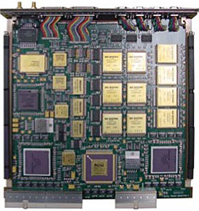
The heart of the DRS processing system is a RAD-750 Central Processing Board that is a single-card computer manufactured by BAE Systems in Manassas, Va. The processor can endure radiation doses that are a million times more extreme than what is considered fatal to humans. The RAD750 CPU itself can tolerate 200,000 to 1,000,000 rads. Also, RAD750 will not suffer more than one event requiring interventions from Earth over a 15-year period. The CPU has 10.4 million transistors. The RAD750 processors operate at up to 200 megahertz, processing at 400 MIPS. The CPU has an L1 cache memory of 2 x 32KB (instruction + data) – to improve performance, multiple 1MB L2 cache modules can be implemented depending on mission requirements. RAD750 operates at temperatures of -55°C to 125°C with a power consumption of 10 Watts. The standard RAD750 system can tolerate 100,000rads.
The Dynamics Control Software conducts ten calculations per second involving the position and attitude provided from the drag-free sensors, and the attitude and rates of the spacecraft to yield force and torque commands sent to the colloid thrusters to act on the spacecraft.