
JPSS-1 – Joint Polar Satellite System
JPSS, the Joint Polar Satellite System, is the next-generation polar-orbiting operational environmental satellite system of the United States of America under operation by the National Oceanic and Atmospheric Administration and NASA. Satellites in polar orbits build one of two critical segments of an operational weather forecasting and environmental monitoring capability, the other being high-orbiting satellites in Geostationary Orbit that deliver overview data products at fast revisit times to complement the less frequent but more extensive atmospheric readings taken by the polar orbit segment.
As an integrated system, JPSS has a number of objectives including the improvement of the timeliness and accuracy of severe weather event forecasts, the provision of advanced atmospheric data products, the collection of imaging products for fire, volcano and oil tracking, the transmission of data products to field terminals and the continuation of long-term climate observations and critical environmental data products.

Under JPSS, NOAA is the operator of the program and responsible for data acquisition, analysis and product distribution while NASA acts as the acquisition agent for the satellite, instruments, launch vehicle and ground systems; also leading program systems engineering and mission definition.
JPSS represents a major technological and scientific step to improve environmental, weather, climate and oceanographic science and help in operational applications. The National Weather Service will be responsible for the operational exploitation of JPSS data products for medium- and long-term weather forecasting with increased speed and accuracy. Climate products collected by JPSS include thirty different Environmental Data Records identified as essential parameters for atmospheric, land, ocean, climate and space environment assessments.
It is commonly agreed upon that the introduction of weather satellites in the 1960s had an impact significant enough to divide the history of meteorology into a pre-satellite and post-satellite era. Like the Space Race of the 50s and 60s, the initial efforts in space-based meteorology were motivated through military prospects. Back then, reconnaissance satellites used physical films to capture imagery of foreign territory and there was strong desire to ensure each roll of film was put to good use – requiring a way of knowing when cloud-free views of targets of interest would be available.
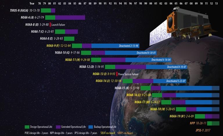
Since those early days, the U.S. operated two separate polar-orbiting environmental satellite programs: NOAA’s Polar Orbiting Operational Environmental Satellite series (POES) and the Defence Meteorological Satellite Program (DMSP) operated by the U.S. Air Force. Efforts began in 1994 to consolidate both satellite series into a single program called National Polar-orbiting Environmental Satellite System, or NPOESS. Under NPOESS, NOAA was given responsibility over the afternoon orbit segment and the Air Force’s Defence Weather Satellite System would be operated in a morning orbit with additional data coming from Europe’s MetOp satellites in a mid-morning orbit.
As a tri-agency effort, NPOESS ended up a fiasco, overrunning its original budget by a factor of two, encountering technical issues on the instrument side, and having to undergo several re-structuring efforts as executing the program between three agencies with different objectives and long-standing acquisition procedures proved extremely difficult. The White House hit the emergency brake in 2010 when it decided the to split the two branches up once again with NOAA & NASA’s Joint Polar Satellite System in the afternoon orbit and the Defence Department’s Defence Weather Satellites System DWSS in the afternoon orbit, operating as separate systems but sharing data.
As a relic of the original NPOESS program, the NPOESS Preparatory Project (NPP) launched the Suomi NPP Satellite in October 2011 to act as a pathfinder for JPSS and bridge a gap until the operational JPSS satellites can be readied for launch – originally expected in 2015.
The Defence Weather Satellite System was canceled in 2012 and the Air Force expects the current DMSP architecture to remain operational through 2021 with a projected launch date for the Weather Follow-On Program (WFO) in 2022. Additionally, the Air Force has entered into agreements to receive data from weather satellites of allied nations including Europe, Korea and India to patch potential gaps arising over the next decade.
For the civilian segment operated by NOAA, current plans call for two operational JPSS satellites to be launched in order to sustain operations through 2028 in the planned afternoon orbit segment. Morning orbit data will be procured through EUMETSAT’s MetOp satellites.
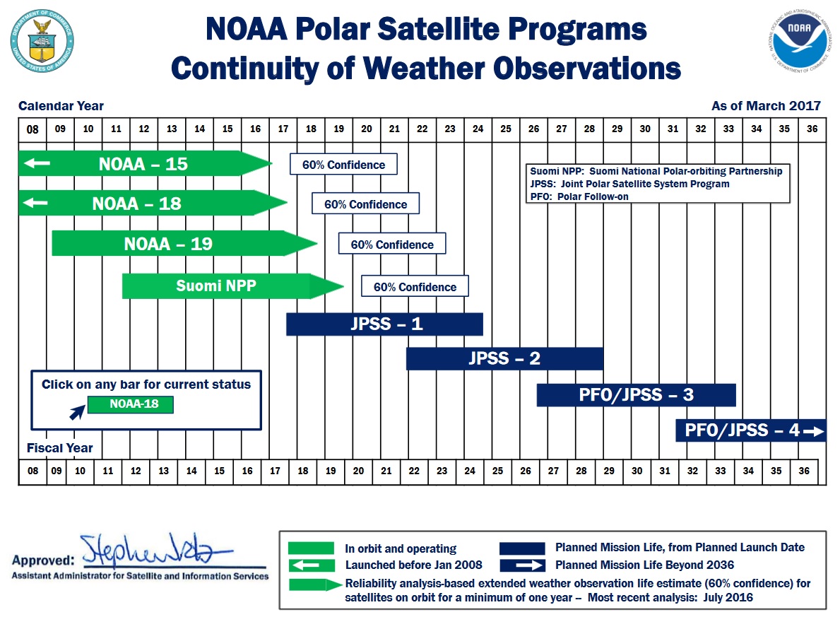
Transitioning into JPSS, NASA and NOAA managed to remain on budget and schedule for the launch of JPSS-1 in 2017 atop a Delta II rocket and JPSS-2 in 2022 in order to minimize any potential loss of continuity of data in the afternoon orbit segment. A number of industry partners have been involved in the JPSS project with Ball Aerospace acting as prime contractor for JPSS-1 and Orbital ATK selected to build the JPSS-2 spacecraft. Instruments hosted on both spacecraft are built by Ball, Raytheon, Exelis and Northrop Grumman.
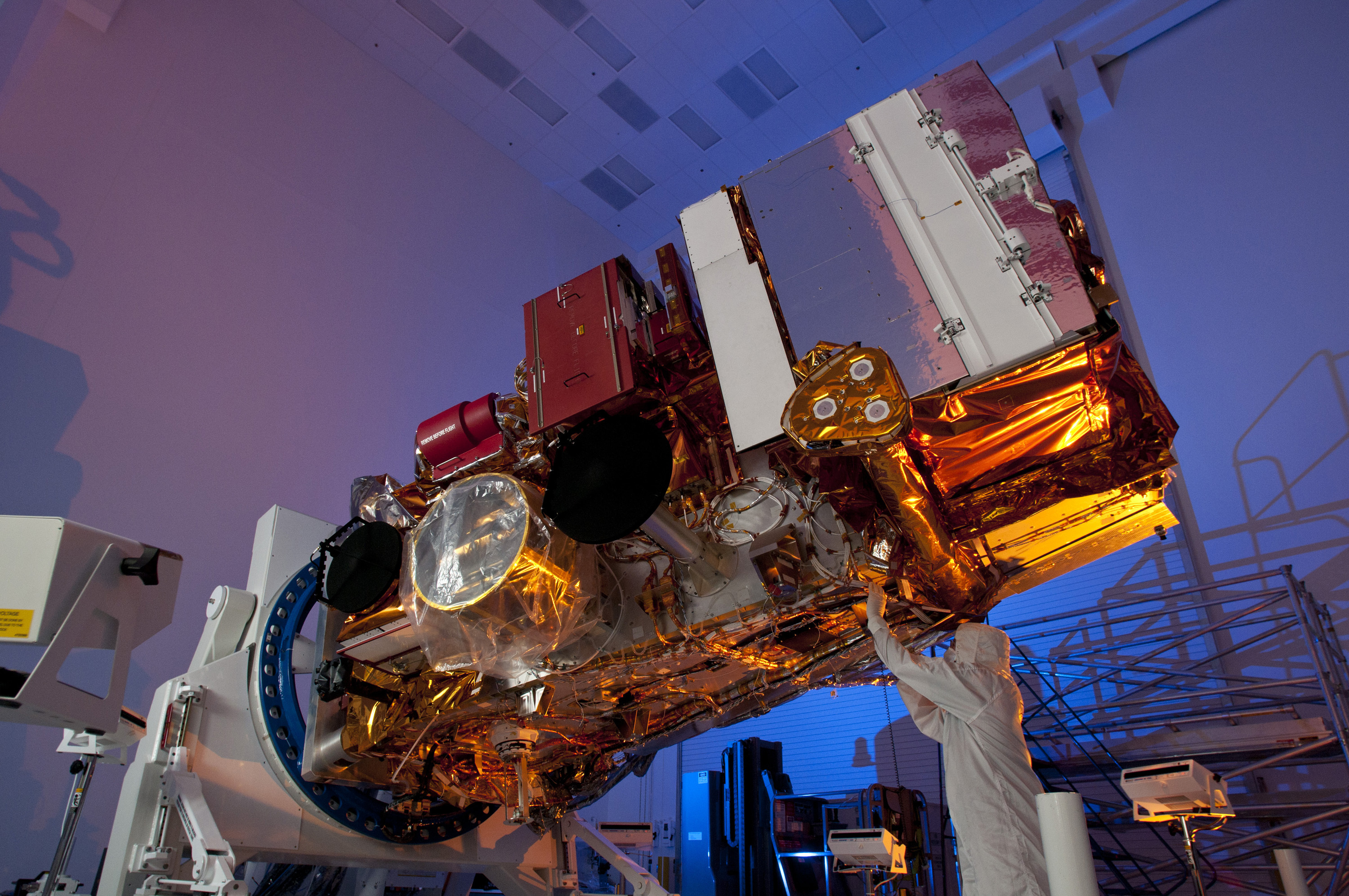
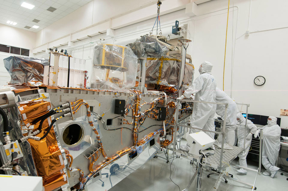
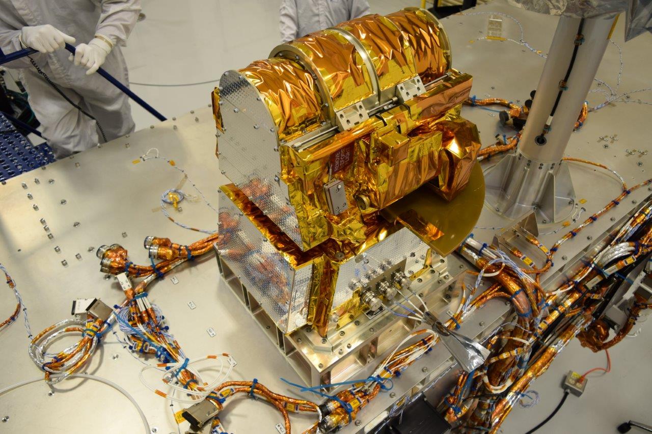
Final contracts for JPSS-1 and its instruments were signed in mid 2012 and the mission cleared its Delta-Critical Design Review that December and was cleared to enter the production stage with bus integration taking place through 2013 leading to the successful first power-on test of the spacecraft platform in March 2014. The first of the satellite’s five instruments began arriving for installation in 2014, the last being the ATMS microwave sounder that began integration with the satellite in February 2016 – some months behind schedule after a technical issue on the instrument was discovered, causing a launch delay from March into the second half of 2017.
With all instruments in place and initial functional checks passed, JPSS-1 entered environmental testing in 2016 to verify the satellite’s performance in the operational environment. The satellite arrived at Vandenberg Air Force Base on September 1, 2017 to enter final pre-launch processing campaign ahead of a November 2017 liftoff atop the penultimate Delta II rocket.

JPSS-1 Satellite Platform
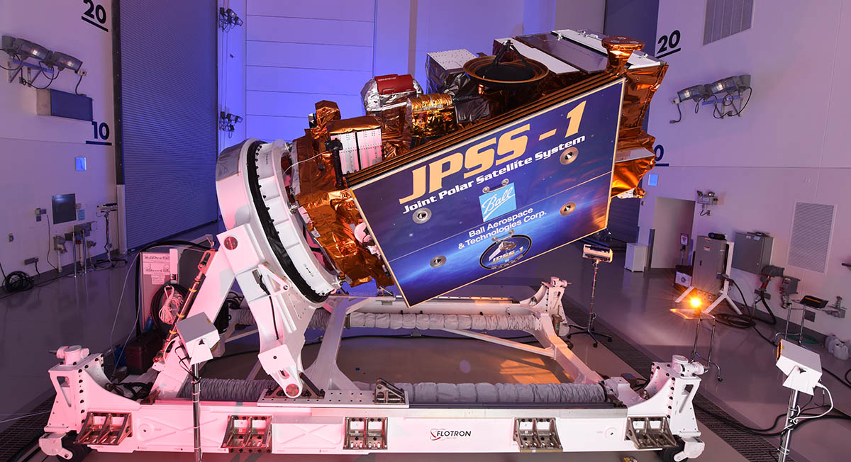
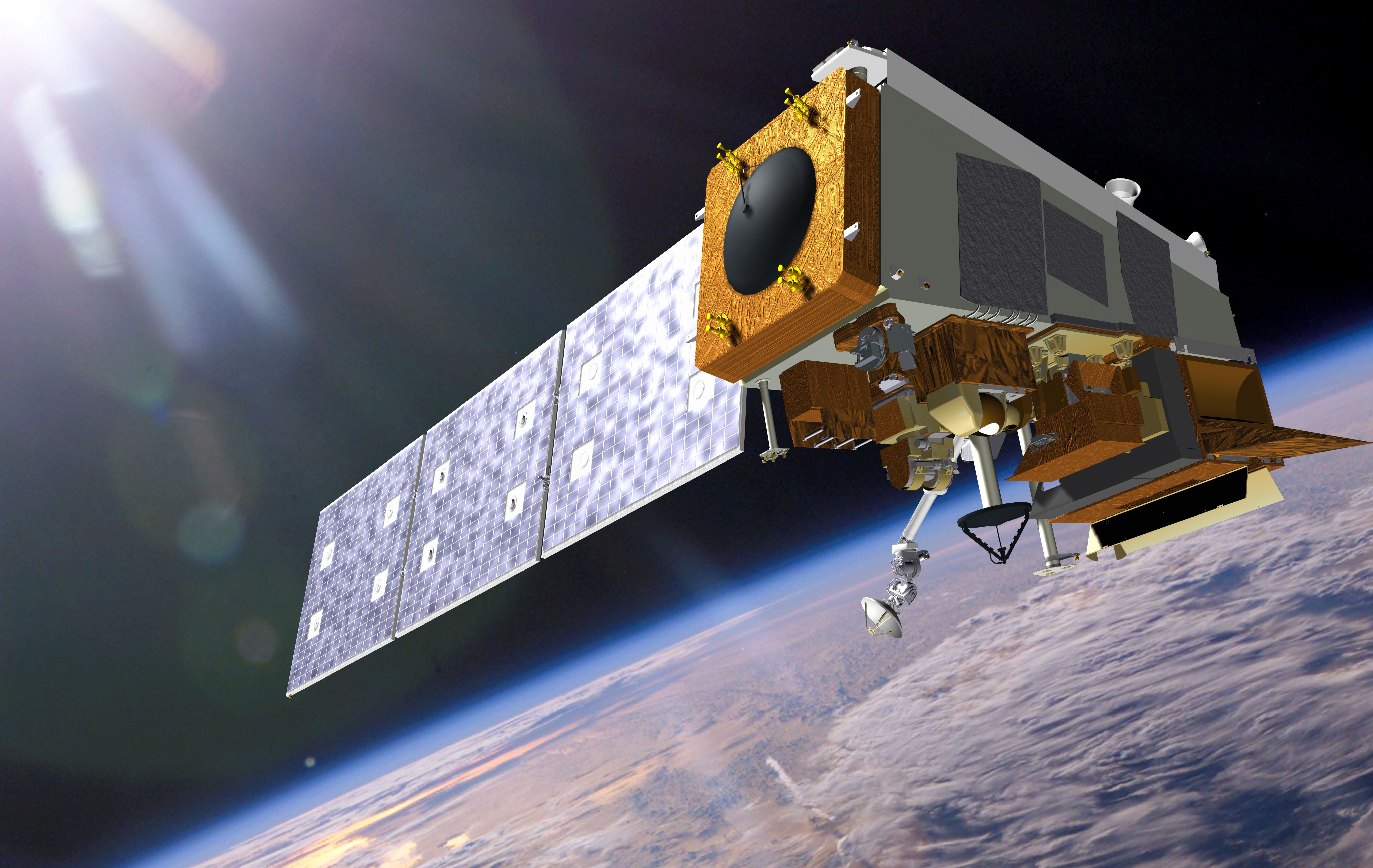
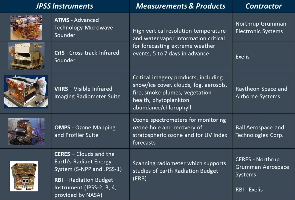
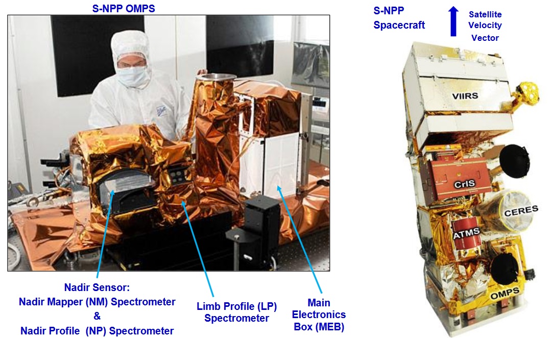
The JPSS-1 satellite is a near carbon copy of the Suomi NPP satellite, based on the Ball Aerospace BCP-2000 satellite platform (Ball Commercial Platform 2000), suitable for satellites in the two-metric-ton mass range. JPSS-1 hosts five science instruments: the Visible/Infrared Imagery Radiometer Suite (VIIRS), the Cross-track Infrared Sounder (CrIS), the Clouds and Earth Radiant Energy System (CERES), the Advanced Technology Microwave Sounder (ATMS) and the Ozone Mapping and Profiler Suite (OMPS).
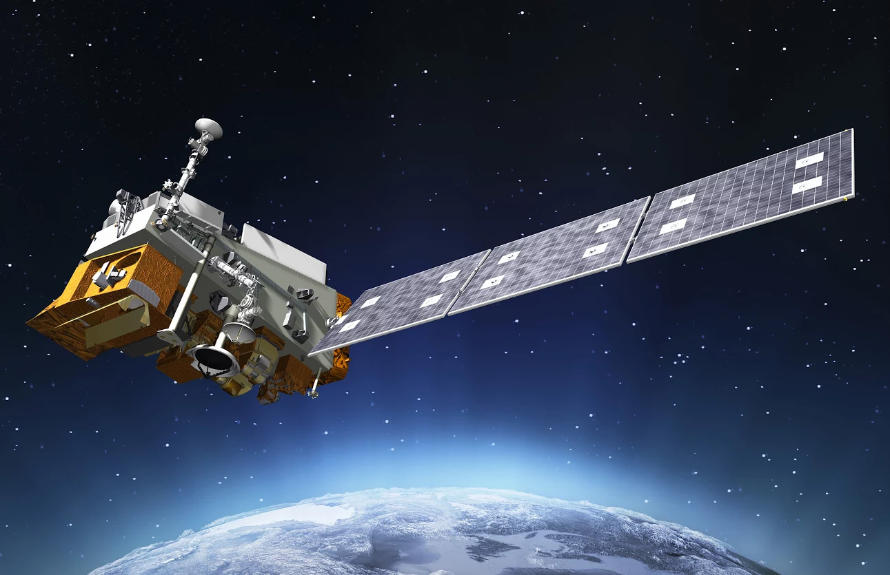
JPSS-1 has a launch mass of 2,540 Kilograms and measures 1.3 x 1.3 by 4.2 meters in dimensions, hosting a total payload mass of around 465 Kilograms. The satellite hosts a single solar array and all five payload instruments reside on one of the large satellite side panels that will be kept in a nadir-viewing orientation for data collection.
Although largely identical to the NPP spacecraft, JPSS-1 implements a number of improvements. The satellite is built for a seven-year mission life requirement whereas NPP was baselined for an operational life of only five years that it surpassed in 2016, continuing to function and shortening the potential gap of NPP going out of service and JPSS-1 arriving in orbit.
Additionally, the satellite’s internal communications system was improved to implement high-speed SpaceWire data interfaces in order to make internal data transfers faster. The communications system switched from X-Band to Ka-Band for faster downlink data rates and to give the satellite the ability to relay its data through the Tracking and Data Relay Satellite System – an important element of an operational mission with the desire of creating a near-real time data pipeline.

BCP-2000 is part of Ball’s BCP product line that covers small satellite buses (BCP-100) and high-performance solutions like the BCP-2000 for intermediate-sized remote sensing missions and the large BCP-4000/5000 platforms for powerful radar and optical imaging payloads. The BCP-2000 satellite platform is designed as a high-performance bus with precise pointing capabilities and power generation for any type of Earth-sensing instrument, yet maintain the flexibility for rapid target selection and slew maneuvers.
The bus has been optimized to offer a large instrument volume. In addition to the volume available above the bus section (constrained by the launch vehicle fairing), BCP-2000 also offers a 127-centimeter deep compartment below the platform’s nadir deck to host payload elements or additional propellant tanks. BCP-2000 implements a fully redundant architecture to provide a probability of success greater than 0.9 over a five-year mission life with additional provisions in place for JPSS-1 and its planned seven-year life.

BCP has flown on seven missions to date including NASA’s QuikScat, ICESat and CloudSat missions that all surpassed their design lives. NPP, previously the heaviest BCP-2000 satellite, also outperformed its planned five-year mission and continued to operate until the launch of JPSS in 2017 with additional years of service expected from the satellite. The JPSS-1 satellite is the heaviest BCP-2000 satellite, weighing in at nearly 600kg more than its NPP predecessor in part due to additional propellant to support the longer service life.
Structurally, the JPSS-1 satellite is primarily using aluminum honeycomb panels as load-carrying elements to form the satellite structure and hold all major subsystem components including the instruments. The majority of the the satellite platform equipment is facilitated in the aft section of the spacecraft and on its zenith (space-facing) panel while the entire nadir panel is dedicated to the five instrument payloads with VIIRS taking up the forward section and the other instruments plus telemetry and direct broadcasting antennas sharing two thirds of the nadir deck.
JPSS-1 hosts one three-panel solar array covered with Gallium-Arsenide solar cells delivering a peak power of 2,775 Watts and an orbit-average power of 1,932 Watts. A Solar Array Drive Mechanism rotates the solar array once per orbit to maintain a normal orientation to the sun for maximum power generation. A single-wing solar array is installed on the anti-solar side of the spacecraft, primarily designed as a thermal control device to preclude thermal input into the cryo radiators of the VIIRS and CrIS instruments.

The satellite employs a pair of Li-Ion batteries to store power for eclipse passes and periods of increased power demand, a change from the NPP satellite that employed less-efficient Nickel Hydrogen batteries. The satellite employs a switch-regulated direct energy transfer system with the battery and its charge/discharge controller tasked with the regulation of the bus voltage to 28 +/-6 Volts.
The JPSS-1 Attitude Determination and Control Subsystem provides three-axis stabilization and attitude maneuvers via four reaction wheels in a redundant arrangement and three magnetic torquer bars for momentum unloading from the wheels and to assist in safe mode control and initial attitude acquisition. Attitude determination in nominal science operations is realized with a two-head Star Tracker system designed to deliver the precise attitude solution needed for the geolocation of VIIRS pixels with an accuracy of +/-200 meters. Three gyroscopes provide rate information for attitude computing between star tracker updates and to measure body rates/acceleration, a pair of Earth sensors is employed for safe mode control along with coarse sun sensors that come into play during initial attitude acquisition and to position the satellite for proper power generation in safe mode events.
All attitude actuators and sensors interface with the spacecraft control processors, achieving a 21 arc-second attitude knowledge and 50 arc-second attitude actuation accuracy. A GPS receiver is used for time synchronization across the various satellite subsystems via a pulse per second signal, for precise position determination with 75-meter accuracy as well as helping in orbit determination.
JPSS-1 hosts a monopropellant propulsion system comprising a central Hydrazine tank located in the aft section of the satellite right above the spacecraft adapter, feeding propellant to eight catalytic thrusters. Compared to NPP, the satellite’s propellant capacity was increased from 324 Kilograms to support a longer service life. Per NPP’s design, the satellite hosts eight 5.3-Newton thrusters for orbital maneuvers and to assist in attitude control when large slew maneuvers are needed. The thrusters use the catalytic decomposition of Hydrazine into gaseous reaction products over a metallic catalyst bed. The catalyst material used on NPP was replaced with a more efficient catalyst on the JPSS spacecraft.
An area where a number of significant changes occurred from NPP to JPSS is the Command and Data Handling Subsystem. NPP used a FireWire data interface with a maximum data rate of 12Mbit/s to route data from the VIIRS, CrIS and OMPS instruments to the onboard data storage and transmitted stored science data to ground stations through a 300Mbit/s X-Band terminal.

The JPSS-1 satellite uses an upgraded SpaceWire architecture for high rate onboard communications and expands its communications capability through the addition of a Ka-Band system that can either transmit to ground stations or relay data via NASA’s Tracking and Data Relay Satellite System.
JPSS-1 has a 343-Gbit Solid State Recorder capable of holding around six orbits worth of Stored Mission Data from all satellite instruments. SMD downlink occurs exclusively via Ka-Band, either though an SMD TDRSS link or the SMD ground link antenna, both operate at data rates of 300 Mbit/s. The mission’s four compatible Ka-Band ground stations are Svalbard, McMurdo, Fairbanks and Troll with TDRSS typically used for backup and downlink of high-priority data from weather systems of interest.
Command uplink and Telemetry downlink continues to use an S-Band terminal with command data rates of 125 or 1,000bps and telemetry rates of 1,024, 4,096 or 16,384 kbit/s when going through TDRS and maximum data rates of 128 kbit/s for uplink and 524,800kbit/s for downlink, using nadir-pointed antennas for TT/C ground station links and a zenith-facing antenna for TDRSS communications.
JPSS-1 will continue the provision of High Rate Data products in real time via a dedicated 15 Mbit/s X-Band feed at 7,812 MHz. The direct broadcast feed can be received by any equipped field terminal and includes various data products including multi-channel imagery from VIIRS, instrument science data, instrument engineering data and instrument telemetry data.
Instruments

The JPSS-1 and 2 satellites use nearly identical instrumentation as the NPP satellite, hosting standard instruments that would be expected from a weather satellite as well as specialized instruments to collect additional parameters for scientific and operational applications.
The two primary meteorological instruments installed on JPSS are VIIRS (Visible Infrared Imager Radiometer Suite) developed by Raytheon Space and Airborne Systems and ATMS (Advanced Technology Microwave Sounder) provided by Northrop Grumman. CrIS, the Cross-Track Infrared Sounder, was developed by ITT Exelis and provides complementary measurements to VIIRS; the Clouds and the Earth’s Radiant Energy System, coupled with the Radiation Budget Instrument, was provided by Northrop and Exelis; and the Ozone Mapping and Profiler Suite was developed by Ball Aerospace to track ozone hole recovery and provide data for UV index forecasts.
VIIRS
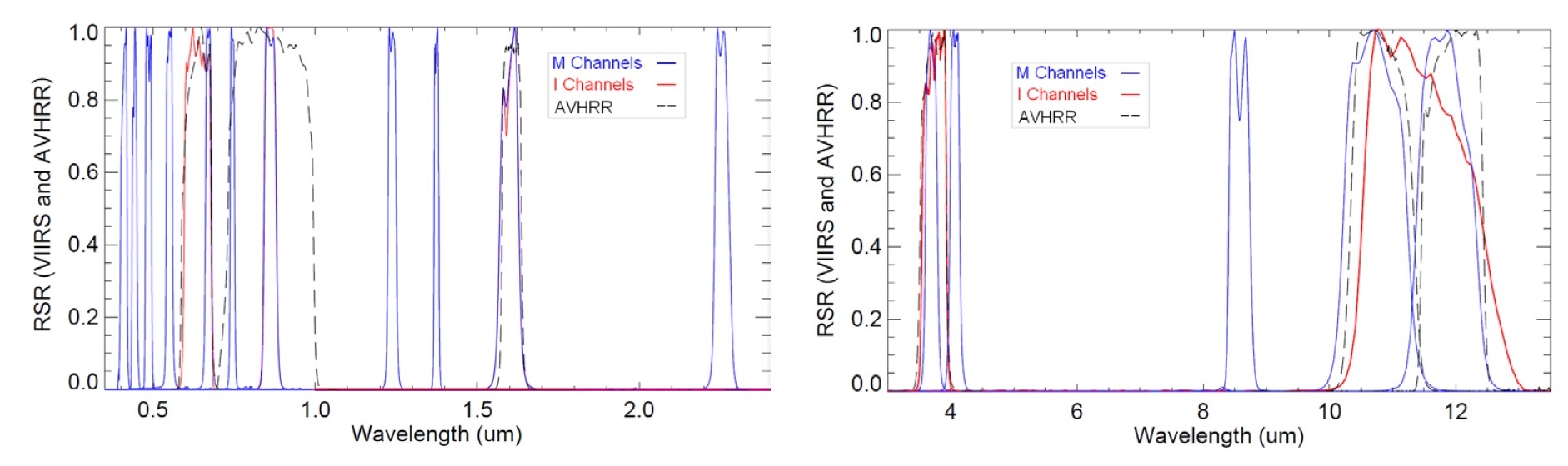
VIIRS is one of two critical meteorological instruments on the JPSS satellite (the other being ATMS) and is responsible for the collection of imagery of clouds under sunlit conditions in a dozen spectral bands and provide coverage in a number of infrared bands for all-day coverage including nighttime scenes. The instrument represents a powerful combination of the spatial resolution of the Operational Linescan Imager hosted by DMSP and the radiometric and spectral accuracy of the Advanced Very High Resolution Radiometer flown on NOAA and EUMETSAT spacecraft starting in 1998.
Given its spectral abilities, VIIRS will be tasked with multi-band imaging for the acquisition of high-resolution atmospheric imagery and the generation of a number of applied products including imaging of hurricanes and the detection of fires, volcanoes, smoke and atmospheric aerosols. Through its infrared channels, VIIRS can deliver high-resolution maps of sea surface temperature and provide a range of ocean color products. The instrument draws heritage from its predecessors on DMSP and NOAA satellites as well as the MODIS and SeaWiFS instruments flown on the Terra and Orb-View 2 satellites.
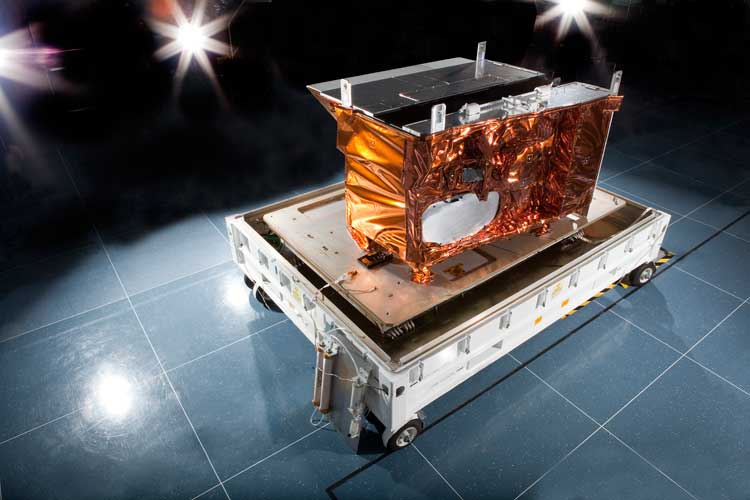
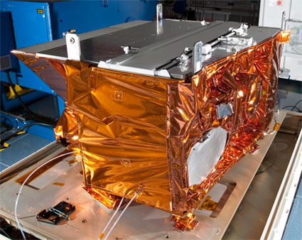
VIIRS has a total mass of 275 Kilograms, measures 137 by 149 by 89 centimeters in dimensions and resides in the forward section of the satellite’s nadir panel. The opto-mechanical radiometer instrument covers a total of 22 channels in the Visible & Near Infrared, Short-Wave Infrared and Long-Wave Infrared.
The VIIRS instrument comprises a cross-track rotating telescope that sweeps out the image swath perpendicular to the satellite’s travel direction, operating in the whiskbroom scanning principle to achieve a wide swath of 3,040 Kilometers, corresponding to a field of view of 55.8 degrees. The instrument has a Rotating Telescope Assembly of 20 centimeters which is of SeaWiFS heritage and has excellent straylight performance.
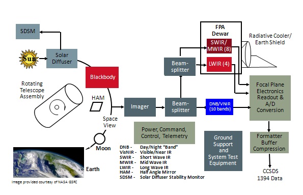
After a set of foreoptics comes a beamsplitter unit (dichroic element) that transmits the visible and near-infrared wavelengths towards the 10-band VIS/NIR focal plane kept at ambient temperature and reflects infrared wavelengths onto a second beamsplitter which separates the shortwave and long-wave infrared bands to direct them to their specific focal plane assemblies kept at cryogenic temperatures within a dewar device to achieve the required radiometric performance.
The VIS/NIR focal plane assembly covers ten channels, nine spectral bands and a specialized panchromatic Day-and-Night Band (DNB); the SWIR focal plane covers eight bands and the LWIR detector assembly has four spectral bands. 32 detector lines make up each of the ten VIS/NIR bands vs. 16 line detector elements for each of the infrared channels. The line elements are oriented in the along-track direction in order to create a parallel coverage of 11.87 Kilometers along-track in one sweep in the cross-track direction.

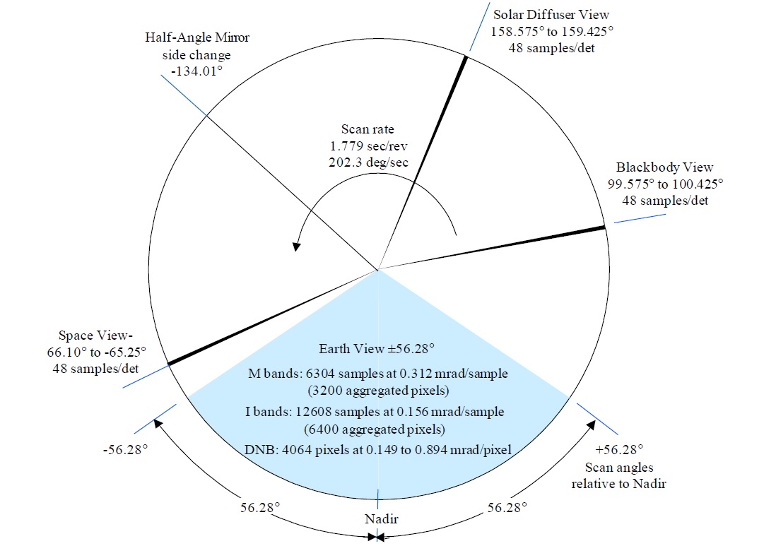
One cross-track scan period is 1.786 seconds in length which, combined with the satellite’s orbital speed (a function of altitude), allows for continuous scanning of the 3,040-Kilometer wide swath, biting off 11.87km for each successive scan.
Given the instrument’s scanning design, the spatial resolution achieved at nadir will be highest – 0.74 by 0.26 Kilometers and 0.37 by 0.38km (along x cross-track) for the VIS/NIR channels, and 0.37 x 0.38 / 0.74 x 0.78 km for the infrared channels to a lowest resolution on the edge of the swath between 0.8 x 0.8 to 1.6 x 1.6 Kilometers. [The imaging bands “I” provide a resolution twice in size to the radiometric bands “M” and typical data products will be produced at coarser resolution by aggregating onboard data, see below.]

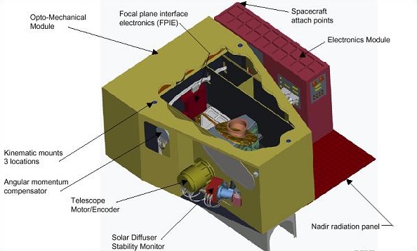
The VIIRS optical segment has an 18.4-centimeter aperture and hosts an off-axis Three-Mirror Anastigmatic telescope assembly that rotates 360° to scan the Earth scene, pass by the internal calibration sources on every revolution and detect external calibration sources – cold space and the Moon. A rotating Half Angle Mirror (HAM) directs the light out of the telescope and to the aft-optics assembly, an all-reflective four-mirror anastigmat, the beamsplitters and their associated folding mirrors and the back-end optics which include microlenses for the cooled focal planes. VIIRS has a focal length of 114 centimeters and all optical elements use advanced technologies including diamond point turning manufacturing techniques on the mirrors.
VIIRS has three focal planes and four Focal Plane Arrays, one for the specialized Day-Night Band and one for the VIS/NIR, SWIR, LWIR focal planes. The instrument features band-to-band co-registration and all spectral channels use Readout Integrated Circuits for the detector readout.

The Day-Night Band covers a broad panchromatic spectral area from 500 to 900 nanometers and employs a CCD detector array with four light-sensitive areas, three employ Time-Delayed Integration and all operate at different gain stages (119,000:477:1) to achieve very large dynamic range of 45 million to one – allowing the instrument to capture data in daylight scenes and low-light conditions down to a quarter Moon.
Two of the detectors operate at the high-gain setting to improve the signal to noise ratio at low signal levels and to eliminate hot pixel effects from high-energy particle hits. Given the swath width, DNB delivers global coverage for cloud imagery with a 12-hour revisit time, making it a powerful tool for weather now- and forecasting.

DNB is a low-light visible-band sensor using reflected moonlight to sense clouds, fog and surface features such as snow cover in addition to emitted light from cities, fires, gas flares and other natural or man-made sources. Data from DNB is used operationally for marine dense fog advisories, snow field detection, sea ice tracking, volcanic ash monitoring and other operational areas. DNB imagery is available at a resolution of 742 meters across the entire swath width.
The nine VIS/NIR detector arrays employ PIN (Positive Insulator Negative) diodes kept at ambient temperature while the two infrared focal planes host photovoltaic (PV) detectors with an element spacing of 12 µm. These are kept at a temperature of 80 Kelvin, housed in a dewar and connected to a passive cryoradiator facing cold space to deliver the thermal environment needed for the reduction of dark currents.

Each focal plane array is connected to the VIIRS instrument computer via a Readout Integrated Circuit, transmitting the analog charge signals for analog-to-digital conversion using 12-bit quantization followed by onboard data processing. The DNB uses 13- and 14-bit quantization for the low/medium and high-gain stages, respectively, in order to achieve the fine radiometric resolution across the entire dynamic range. As part of data processing, the VIIRS instrument computer selects the most sensitive DNB gain stage that is not showing saturated pixels for downlink/storage while the other readouts are deleted.
The radiometric bands take 6,304 samples per scan while the imaging bands collect 12,608 samples to achieve their required resolution. These samples then undergo aggregation into pixels, essentially binning successive samples into a single value to reduce data volume. At nadir, three scans are aggregated into a pixel, starting at a scan angle of 31.7° (523km off-nadir) the aggregation is reduced to two scans per pixel and no aggregation is employed at scan angles of 44.9° or greater (884km off-nadir) since the distance between the satellite and the sampled area grows considerably and reduces resolution.
This aggregation yields 3,200 and 6,400 pixels across the swath width for the radiometric and imaging bands, respectively. The dual-gain channels (M1 through M5, M7 & M13) are left without aggregation to yield finer resolutions of 259 meters cross-track at nadir. The Day-Night Band is another exception, employing a more vigorous sub-pixel aggregation in along and cross track with 32 distinct aggregation modes to yield uniform horizontal sampling distances across the entire swath.
An additional geometric intricacy of VIIRS is the “bow-tie effect”. The instrument’s detector size and scan timing are designed such that the scan width at nadir is the same as the traveling distance of the sub-satellite point in one scan period – leaving no gap between successive scans and avoiding unnecessary data volume created by overlap.
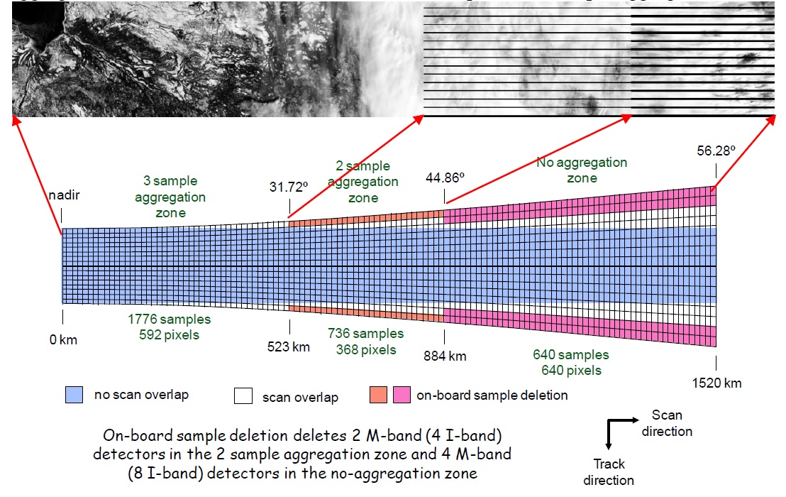
However, the ground sample distance in the along-track direction grows to up to 28.5 Kilometers with increasing scan angle as a result of the greater distance between the satellite and the sampled area. This results in a considerable scan overlap at scan angles larger than 19 degrees. To save downlink bandwidth, the VIIRS data processing system will eliminate the radiometric readings from overlapped along-track pixels at scan angles over 31.7° and assign fill values.
To meet its radiometric performance requirements, VIIRS relies on its onboard calibration devices. Calibration of Reflective Solar Bands (0.4-2.25µm) is accomplished with a solar diffuser that is illuminated for one minute once per orbit as the satellite passes from orbital night into daylight near the South Pole, providing a uniform illumination of all detector arrays. Taking into account the illumination geometry and the Bi-directional Reflectance Distribution Function of the diffuser, the reflected radiance can be computed accurately for comparison with the measured values.

As a cross-check mechanism for degradation of the solar diffuser, JPSS hosts a Solar Diffuser Stability Monitor which compares directly measured sunlight to that reflected from the diffuser to track degradation for adjustment of the radiance reference calculation.
For calibration of the Thermal Emissive Bands (3.74-12.01µm), JPSS employs an Onboard Calibrator Blackbody that is kept at a constant elevated temperature as a high-temperature reference illumination source that is scanned on each revolution of the Rotating Telescope Assembly (providing 48 samples). The blackbody is kept at a time constant temperature using redundant heater elements and six embedded thermal sensors plus 14 thermistors to track the temperature of the blackbody surroundings and optical path to correct for thermal emission from the mirrors and optics elements. The low-temperature reference is provided by scanning cold space for 48 samples on each 360° rotation of the telescope.
ATMS

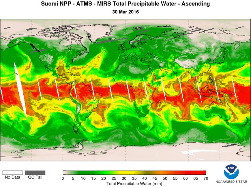
ATMS, the Advanced Technology Microwave Sounder, is a multi-channel, polarization-sensitive microwave-sensing instrument that picks up Earth’s natural microwave emissions from which atmospheric temperature and moisture profiles can be retrieved. It is one of two critical meteorological instruments on the JPSS satellites, the other being VIIRS. Combined, the two provide all necessary information for tracking of adverse weather and numerical weather prediction.
The ATMS instrument installed on JPSS is nearly identical to the system installed on Suomi-NPP, tasked with the collection of temperature and moisture profiles, integrated water vapor content, cloud liquid water content, precipitation rate, snow cover and sea-ice concentration. Through the use of advanced technology, ATMS can combine the capabilities of three heritage microwave sounders in a single instrument unit.
ATMS covers 22 microwave channels which, combined with the CrIS instrument, will yield atmospheric temperature profiles at one Kilometer vertical resolution and an accuracy of 1 Kelvin as well as moisture profiles accurate to 15% for two-Kilometer vertical layers.
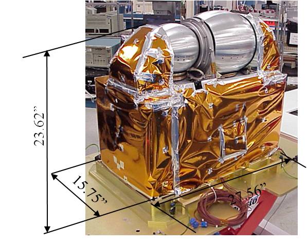
The 85-Kilogram ATMS instrument is 70 by 60 by 40 centimeters in size and requires up to 200 Watts of electrical power. It achieves a nadir resolution of 15.8 to 74.8 Kilometers and covers a broad spectral range of 23 to 183 Giga Hertz. The instrument collects temperature soundings from the surface to the upper stratosphere (around 45km in altitude) and humidity soundings from the surface to around 15 Kilometers.
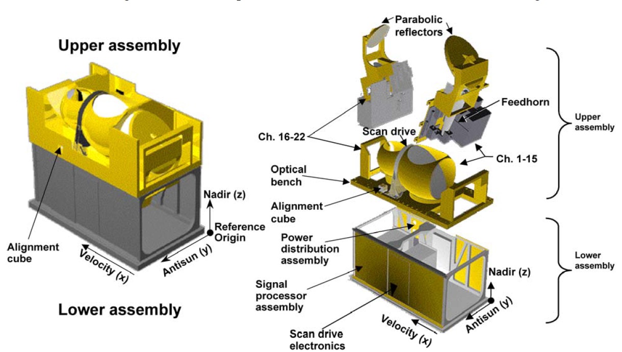
ATMS consists of two components, an Upper Assembly that hosts the optics and feed horns installed on an optical bench and a Lower Assembly that houses the various receiver units and associated electronics. As a cross-track scanning instrument, ATMS hosts a rotating reflector that sweeps out the instrument’s scanning pattern to cover a broad ground swath with collected radiation being reflected to a pair of RF feed subsystems – one for 15 channels below 60 GHz with a beam width of 5.2° for the two lowest channels and 2.2° for the others while the other antenna feeds seven channels above 60 GHz with a beam width of 2.2° for the 89 GHz channel and 1.1° for the remaining six. Each RF feed system consists of two feed horns, dichroic beam splitters and parabolic reflector elements.
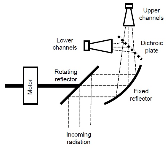
Plane reflectors within each RF feed subassembly are installed at a 45° tilt angle to the scan axis so that radiation from a direction perpendicular to the scan axis is directed into a direction parallel to the scan axis, achieving a 90° reflection. Radiation collected by the motor-driven rotating reflector is re-directed and focused by stationary parabolic reflector elements onto a dichroic plate which separates the beam according to the different beam width requirements of the instrument, meaning channels 1 and 2 (beam width 5.2°), channels 3-15 (2.2°), channel 16 (2.2°) and channels 17-22 (1.1°) have their own Receiver Subsystems and feed horns.
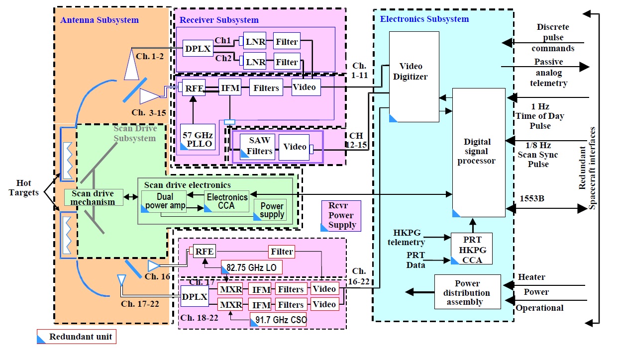
The two largest apertures of the ATMS instrument are used for the 15 low-frequency channels which are also known as the KAV-system since it covers K-Band (Channel 1), Ka-Band (Channel 2) and V-Band (Channels 3-15). The dichroic plate of the system reflects the lower frequencies (Ch. 1 & 2) and transmits those above, splitting the RF energy toward the two feedhorns. The output of the lower-frequency feed enters a diplexer that splits the band limited RF energy into two paths, fed into amplified receiver chains and through bandpass filters centered at 23.8 and 31.4 GHz and a video processing unit for detection.
The output of the higher-frequency feedhorn enters an amplified and bandpass filtered heterodyne receiver with two down-converter/mixer chains using a Local Oscillator tuned to 57.29 GHz to act as referenced phased locked oscillator. A lowpass filtered band is passed through a set of splitters and multiplexers followed by bandpass filters that select channels 3-9; the other band is bandpass filtered using conventional bandpass filters to form channels 10 & 11 and standing acoustic wave filter assemblies for channels 12-15 implemented as four pairs of filters with outputs of each pair connected to amplifiers.
The smaller aperture for channels 16-22 is referred to as the WV-system since channel 16 falls into the W-Band and channels 17-22 into the V-Band range. The signal reflected by the dichroic element – only channel 16 – enters a dedicated feed horn which directs the RF energy into an amplified highpass filtered heteodyne receiver chain where the mixer uses a 82.75 GHZ local oscillator and 4450-6450MHz bandpass filter. The high-frequency segment of the RF energy is split in two paths by means of a diplexer, one path enters a second harmonic mixer that uses the Channel 16 oscillator and a 350-1500 MHz bandpass filter to yield channel 17 at 164-167GHz.
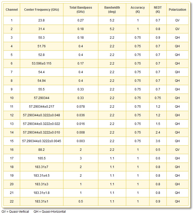

The second path uses a Local Oscillator at 91.655 GHz and a set of filters to produce channels 18-22 centered at 183.31 GHZ with their bandpass varying from channel to channel.
The ATMS scan sequence has been set up elaborately to capture data across a broad, uninterrupted ground swath and provide calibration opportunities for every scan. To satisfy these criteria, ATMS rotates its antenna reflector continuously in the counter clockwise direction but with varying speed across the different scenes viewed every scan period. The scan mechanism is synchronized to the spacecraft via a synchronization pulse sent every eight seconds, on every third revolution of the reflector.
The critical Earth-viewing period of each scan cycle is divided into 96 samples, viewing Earth at 96 different angles.
Since the antenna is in continuous motion, the samples are taken on the fly with each sample representing the mid-point of an 18-millisecond interval, corresponding to an angular sampling area of 1.11°. The instrument measures for off-nadir angles of 52.725°, corresponding to a swath of 2,600 Kilometers.
After maintaining a constant speed of 61.6°/sec for the Earth-scan, the antenna reflector accelerates until reaching a position where it can view a sector of cold space for four consecutive cold calibration measurements (72ms).
It then accelerates again until reaching a zenith position where it is again slowed down to take four measurements of a hot calibration target maintained at the relatively high instrument temperature with sensors keeping track of its exact temperature. Finally, the scan drive motor accelerates again until reaching the starting point for the next 96-sample Earth-scan (1.73 seconds). ATMS can also be operated in a stare mode in any position for extended calibration, if needed.
CrIS
CrIS, the Cross-Track Infrared Sounder, is a high-spectral and high-spatial resolution infrared sounder measuring in over 1,000 channels to deliver three-dimensional soundings of atmospheric temperature, water vapor and trace gases. Still a relatively new type of system, CrIS on the Suomi-NPP mission has become a powerful tool for more accurate, detailed atmospheric observation which, when combined with ATMS microwave soundings yields much improved short-therm weather nowcasting and longer-term forecasting in the three to seven-day range.
CrIS provides the soundings needed for real-time instability assessments and trace gas monitoring for climate science, taking an important position for the operational aspects as well as the scientific data record. A combined CrIS/ATMS data processing pipeline has been developed by NOAA, called NUCAPS, to deliver spectrally and spatially thinned radiances, profiles of temperature, moisture, trace gases and cloud-cleared radiances.
CrIS finds heritage in the HIRS/4 instrument flown on the POES satellites and the AIRS instrument of NASA’s Aqua satellite. The overall objective for the instrument is the daily measurement of Earth’s upwelling infrared radiation to determine vertical atmospheric distribution from the surface to the top of the atmosphere with an accuracy of 1K for temperature, 1% for atmospheric pressure and 20-35% for moisture levels, all provided with a 1.0-Kilometer layer resolution and a measurement cell size of 14 Kilometers.
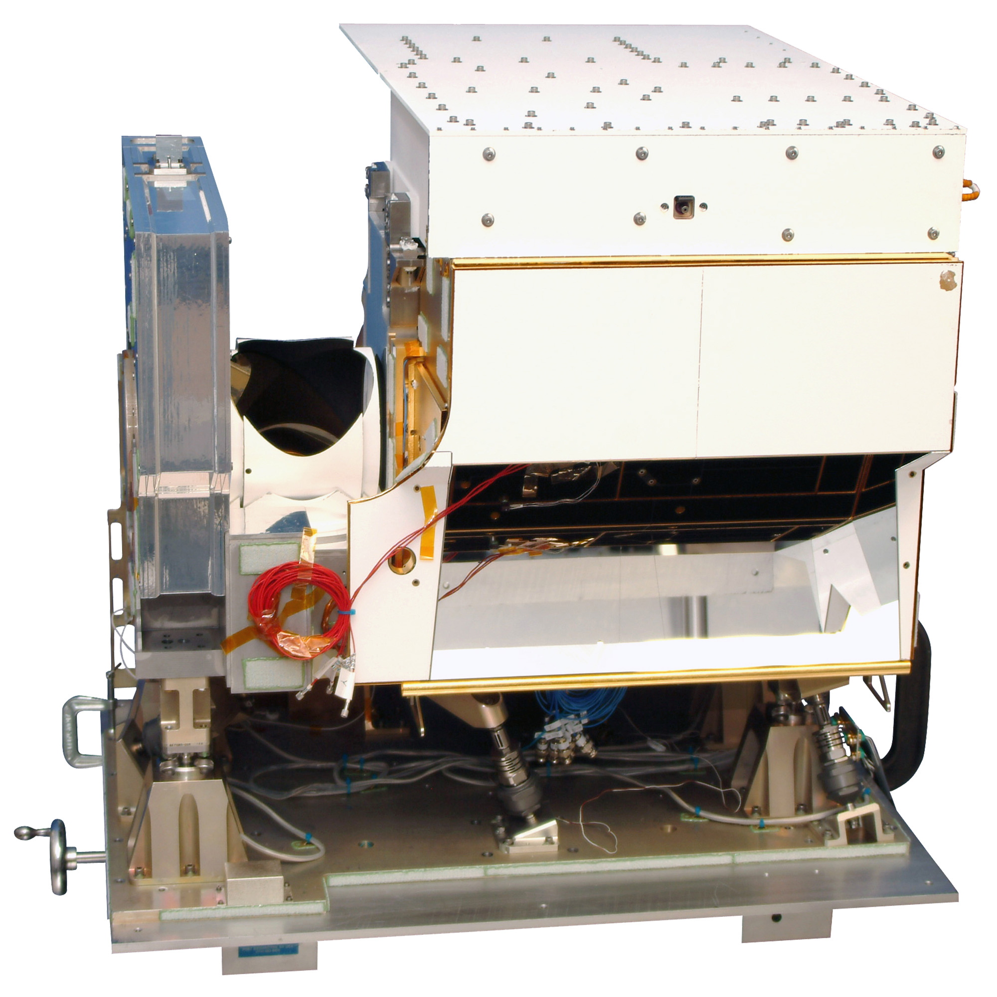
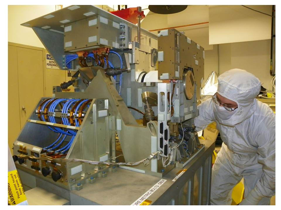
The CrIS instrument weighs 147 Kilograms, draws 110 Watts of power and is 71 by 80 by 95 centimeters in size, hosting a Michelson interferometer sounder with cooled focal plane assemblies.
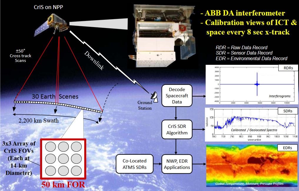
The CrIS instrument comprises six primary building blocks: an optical bench, a scanning telescope, the Michelsen Interferometer with associated fore & aft optics, the PV focal plane arrays, a four-stage passive cooler, and support electronics. CrIS hosts an 8-centimeter clear aperture that allows IR radiation to reach the two-axis step-and-settle scene selection module that provides image motion compensation capability. The scene module is tasked with the selection of the sample area, selecting between thirty Earth Scenes along a +/-50-degree, 2,200-Kilometer swath and placing the instrument’s calibration sources into the optical path.
CrIS uses a three-element all-reflective telescope to focus the incoming infrared radiation toward the interferometer where the wavelengths of the incoming beam are sequentially separated and directed into a cool aft-optics system that focuses the dispersed light onto the photovoltaic detector array.
The interferometer uses a standard plane-mirror Michelsen configuration in which incoming light is split with a beam splitter device onto two optical paths created by flat mirror systems with one path at constant length and the other varied by +/-0.8 centimeters before both reach the detector, creating an interference pattern on the detector that is dependent on the path difference which is precisely known through accurate measurement of the moving mirror position. An interferogram is created by taking measurements of the signal at many discrete positions of the moving mirror. Fourier transformation then converts the interferogram into a high-resolution spectrum (with resolution depending on the number of discrete measurements).
The major advantage of Fourier Transform Spectrometry over dispersive spectrometers (grating or prism spectrometers) is a higher spectral resolution and much improved signal to noise ratio since the interferometer’s detector effectively monitors all wavelengths simultaneously throughout the measurement as opposed to grating spectrometers where the measured wavelength varies across the detector.

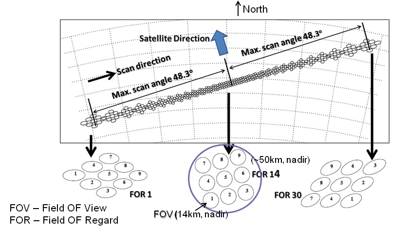
The CrIS instrument collects data from nine Instantaneous Fields of View (IFOV) per Earth Scene (in a 3 x 3 grid) with thirty such grids collected each measurement interval across the 2,200km ground swath. A total of 1,305 spectral channels are recorded by the instrument: 159 in the Short-Wave Infrared range of 3.92 to 4.64 µm; 433 in the Mid-Wave Infrared from 5.71 to 8.26 µm and 713 channels in the long-wave infrared range of 9.14 to 15.38 µm with spectral resolutions of 9, 6 and 4.5 nanometers, respectively.
All three Focal Plane Array Assemblies for each IOFV are co-registered to view the same region of Earth’s atmosphere. The four-stage cryo-cooler, using passive radiator elements, is tasked with cooling the photovoltaic detector arrays to 81 Kelvin on the LWIR detector and 98K for MWIR and SWIR to reduce detector noise, requiring the detectors and aft optics to be thermally decoupled from the rest of the instrument which operates at the ambient spacecraft temperature.
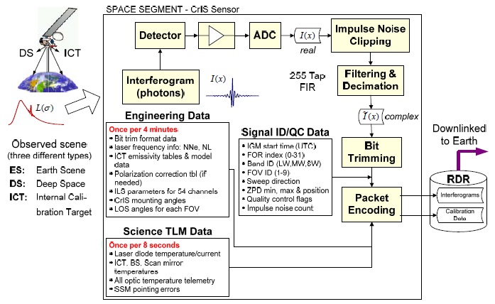
The Detector Preamplifier Module interfaces with the PV arrays through three signal flex cable assemblies that exit the sealed detector module through a warm signal flex – vacuum bulkhead assembly to reach the warm electronics Circuit Card Assemblies where signal amplification and digitization occurs. The primary output of the instrument are the interferograms from 27 infrared detectors that cover three bands and nine IFOVs.
Calibration of the Michelsen Interferometers uses Laser Wavelength Calibration for alignment calibration and to check the moving mirror position monitor while a Neon bulb acts as calibration source for spectral calibration. The internal calibration target is scanned every eight-second repeat interval, using a highly emissive, deep-cavity blackbody with a temperature knowledge better than 80 milli-Kelvin.
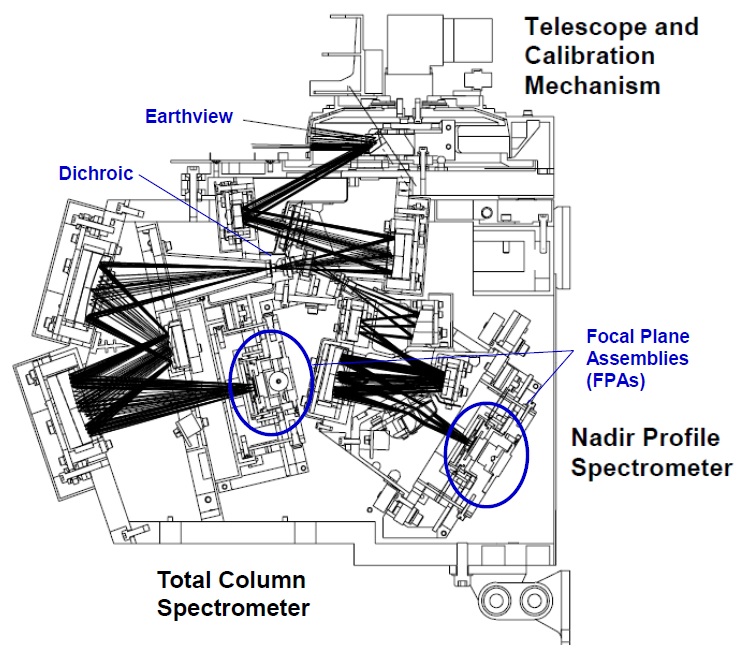
OMPS
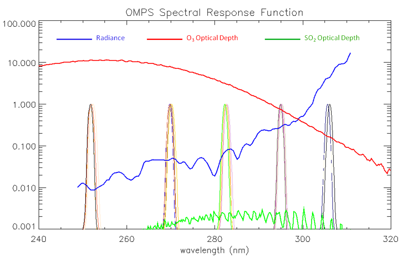
OMPS, the Ozone Mapping and Profiler Suite, is a specialized instrument for the creation of global ozone concentration maps needed by the scientific community for tracking ozone hole recovery and understanding the role of ozone in various atmospheric processes while operational weather forecasters need ozone measurements for UV index prediction.
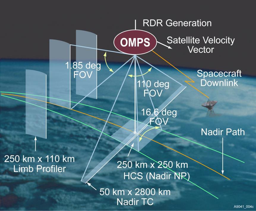
Ozone is a critical atmospheric constituent that absorbs ultraviolet radiation from the sun and reduces its influx to the surface. OMPS, a limb- and nadir-scanning UV hyperspectral imaging spectrometer, is tasked with measuring the distribution of ozone on a global scale and also provides ozone altitude profiles, continuing a three-decade record of these vital climate parameters.
The 56-Kilogram instrument comprises two sensors – a nadir sensor to generate total column ozone measurements and a limb sensor gathering ozone altitude profile data through the limb scattered solar radiance.

The OMPS Nadir Viewing Instrument facilitates a pair of co-registered spectrometers fed by a common wide-field telescope for ozone column observations and nadir profiling observations. The instrument’s telescope uses a three-mirror, near telecentric, off-axis design with a field of view of 110 degrees which is concave in the anti-ram direction by 8.5-degrees at the cross-track edge in order to maintain straight entrance slits for the imaging spectrometers. Mirrors used on OMPS are made of a glass that shares the thermal expansion of titanium.
The Total Column Spectrometer uses the entire 110° field of view to measure a ground swath of 2,800 Kilometers to achieve daily global coverage. The spectrometer is sensitive for wavelengths of 300 to 380 nanometers and delivers a spectral resolution of 0.45 nanometers.
Its 0.27° wide slit is divided into 35 Instantaneous Fields of View of equal angular extent, corresponding to 35 bins on the Charged Coupled Device detector array which are sized to correspond to 3.35° of the entire scan angle at nadir and 2.84° at 55° off-nadir, creating a uniform ground sampling distance of 50 Kilometers in the cross-track direction. The along-track resolution of the spectrometer is driven by its reporting period, selected at 7.6 seconds to generate total column ozone data with a spatial resolution of 50 by 50 Kilometers at nadir.
The Nadir Profiling Spectrometer, also using a grating design, operates at wavelengths between 250 and 310 nanometers and covers a 250-Kilometer cross-track swath with a 16.6° cross-track field of view and 0.26° slit width. All cross-track pixels are binned spatially and the instrument operates at a 38-second integration time to create a single cell of 250 by 250 Kilometers, co-registered with the mapping spectrometer that delivers the total ozone, surface and cloud cover information needed to extract profiles for the 250km cells.
Both spectrometers use 340 by 740 pixel CCD detectors (column x row) operated in a back-illuminated configuration with a 20 x 25 µm pixel pitch (spectral x spatial). The CCDs are connected to a pre-amplification stage that transmits the analog detector read-outs to the main electronics box where analog-to-digital conversion takes place.
The Nadir Viewing Instrument employs polarization compensators to eliminate polarization effects on the spectral measurements and long-term calibration is provided by regular solar observations with a pair of solar diffuser systems (one used for regular calibration and the other protected by covers for occasional exposure to check degradation on the main diffuser).
All in all, the OMPS nadir-viewing instrument is 31 by 32 by 20 centimeters in size and weighs 12.5 Kilograms
The OMPS Limb Profiler is not flown on the JPSS-1 satellite, but is part of the instrument suite on Suomi NPP and the JPSS-2 satellite.
The Limb Profiler consists of four major elements, the telescope, the spectrometer, a radiator and a calibration mechanism. Three slits, each separated by 250 Kilometers at the limb tangent point (4.25°), deliver light into the spectrometer where it is dispersed by a single prism and directed onto a CCD detector array. To deal with a high dynamic range in the observed scenes, the Limb Profiler employs a beam splitter that divides the scene brightness into three brightness ranges, meaning the instrument captures a total of nine limb images of the dispersed slits.
Each of the three slits has a vertical field of view of 1.95 degrees, corresponding to 112 Kilometers at the limb, allowing the instrument to cover the entire atmosphere from ground level. CCD pixels are spaced every 1.1 Kilometers of vertical image and have a vertical resolution of 2.2 Kilometers. The broad spectral range of the instrument of 290 to 1,000 nanometers allows it to capture radiances in ultraviolet, visible and near-infrared to permit a retrieval of ozone, aerosol and cloud profiles from the tropopause to an altitude of at least 60 Kilometers. The spectral resolution varies from 0.75 nm in the ultraviolet to 25 nm at the 1,000 nm cutoff.
CERES

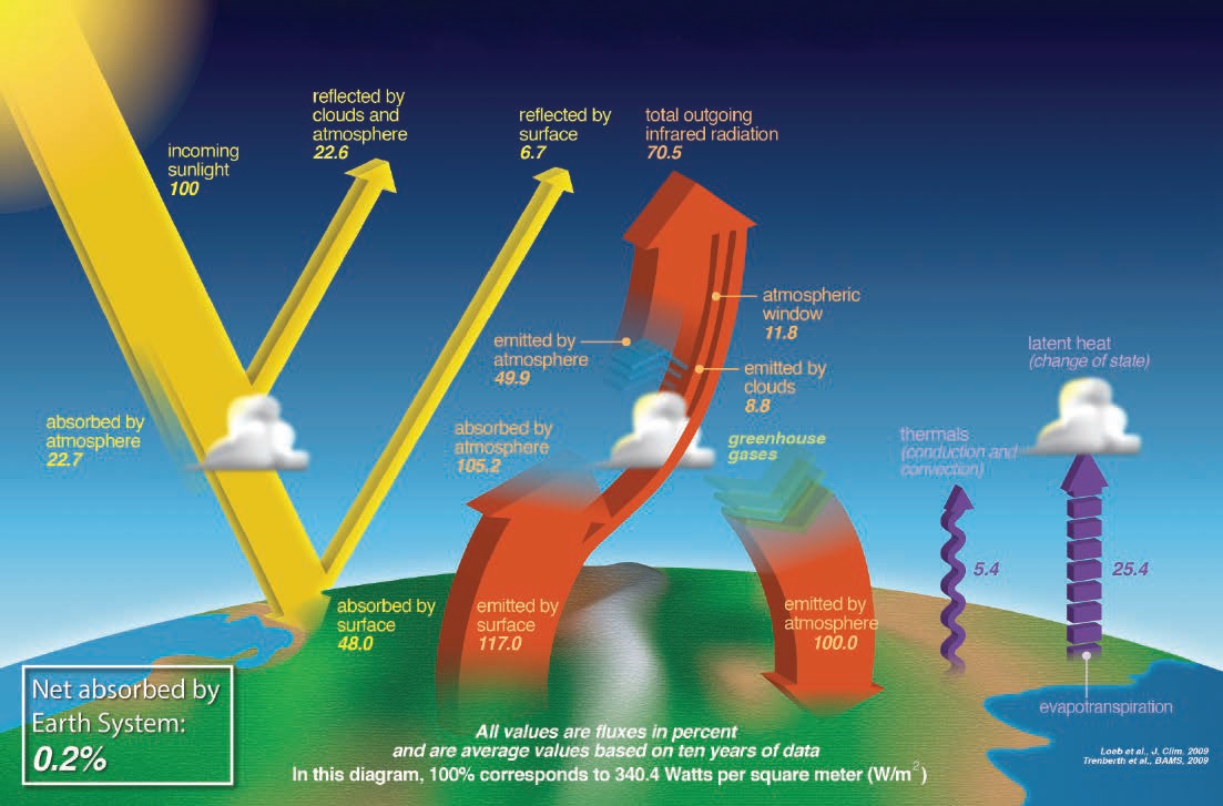
CERES, the Clouds and the Earth’s Radiant Energy System, is a specialized instrument for the measurement of the reflected shortwave and Earth-emitted radiances to continue a long-standing data record of Earth’s energy budget, one of the most critical climate variables. Measurements provided by CERES can help in weather forecasting but are mainly used by the scientific community for climate assessments. CERES data can also be useful in forecasting of large-scale climate events like El Niño and La Niña.
The main objective of the instrument is the measurement of the spatial and temporal distribution of Earth’s Radiant Budget (ERB) components, helping in the quantitative understanding of the links between ERB and the properties of the surface and atmosphere that define the budget. CERES data provides information on the effect of clouds on the energy balance between solar input and radiation output from Earth, one of the largest variables in current climate models.
ERB Climate Data Records have been continuously produced since 1997 when a prototype instrument was deployed on the TRMM satellite and the continuation of this record has been made a priority by NOAA and NASA to allow for a long-term assessment of climate change and further the understanding of interactions of natural and anthropogenic effects occurring on longer time scales. The CERES instruments on the JPSS satellites are planned to provide ERB measurements through the 2020s with sufficient overlap between instruments to accomplish cross-calibration to ensure data accuracy.
In total, CERES measures four parameters: a) the net solar radiation input at the top of the atmosphere, b) downrange longwave radiation at the surface, c) downward shortwave radiation at the surface, and d) outgoing longwave radiation at the top of the atmosphere. These parameters allow a complete assessment of energy input, absorption and output and, when combined with data from other instruments, will enable an examination of the effect of different variables like solar activity, atmospheric dynamics and clouds on the long-term progression of Earth’s climate.
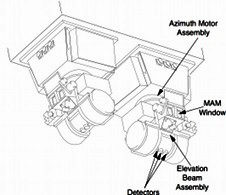
The CERES instrument comprises three principal components: 1) a Cassegrain telescope, 2) a baffle for straylight rejection and 3) a detector assembly with an active and compensating element plus associated read-out and processing electronics. The instrument consists of two identical scanners and has a mass of 114 Kilograms with physical dimensions of 60 by 60 by 58 centimeters per unit.
Light enters through the forward baffle and is focused onto the focal plane using a two-mirror Cassegrain telescope in which both mirrors reside on the optical axis. Employed as detectors within the focal plane are uncooled thermistor bolometers with three spectral channels covered by each of the two radiometers.
The Bolometer Array Instrument is an uncooled infrared imager that does not rely on a cryocooler to keep the detector cooled. Each pixel on the array consists of several layers including an infrared absorbing material and a reflector underneath it that directs IR radiation that passes through the absorber back to the absorbing layer to ensure a near complete absorption. As IR radiation strikes the detector, the absorbing material is heated and changes its electrical resistance which can be measured via electrodes connected to each microbolometer and processed into an intensity read-out.
CERES covers three spectral bands: 1) the VNIR/SWIR channel captures reflected sunlight at wavelengths between 300 nanometers and 5.0 micrometers with an energy accuracy of 1%; 2) the Atmospheric Window from 8 to 12 µm, also known as the Long-Wave Channel, measures Earth-emitted radiation including water vapor; and 3) the Total Channel Radiance captures infrared from 0.35 to 125 µm which includes reflected and emitted radiation of the Earth-atmosphere system with a measurement accuracy of 0.3%.
CERES has an instantaneous field of view of 14 mrad and a field of regard of +/-78° using a limb-to-limb cross-track scanning technique. The spatial resolution achieved at spacecraft nadir is between 10 and 20 Kilometers.
CERES uses a variety of calibration sources to track the accuracy of its bolometer detectors including internal blackbodies and lamps as well as a solar diffuser that allows the shortwave and total sensors to be calibrated against the well known solar irradiance. Calibration of the long-wave channel is accomplished via night-time cloud sensing as a low-temperature point calibration.
Ground Segment
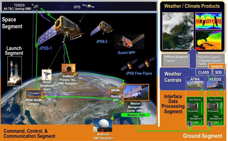
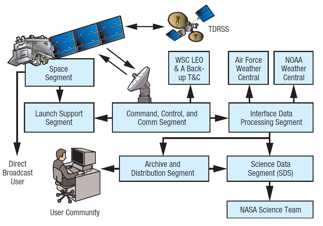
The JPSS Common Ground System has been a major schedule driver in the development of the program. It was awarded to the Raytheon Company in September 2010 and calls for the development of a system for uninterrupted support to meet civilian and defence weather needs through round-the-clock mission planning, data acquisition, processing and distribution. The system is designed for multi-mission use in national and international partnerships and will support over a dozen satellites at any given time in different capacities ranging from simple data routing to a complete commanding, mission planning and data processing service used for JPSS and NPP.
The system comprises three components: a) Command, Control and Communications Segment; b) Interface Data Processing Segment and c) Field Terminal Segment.
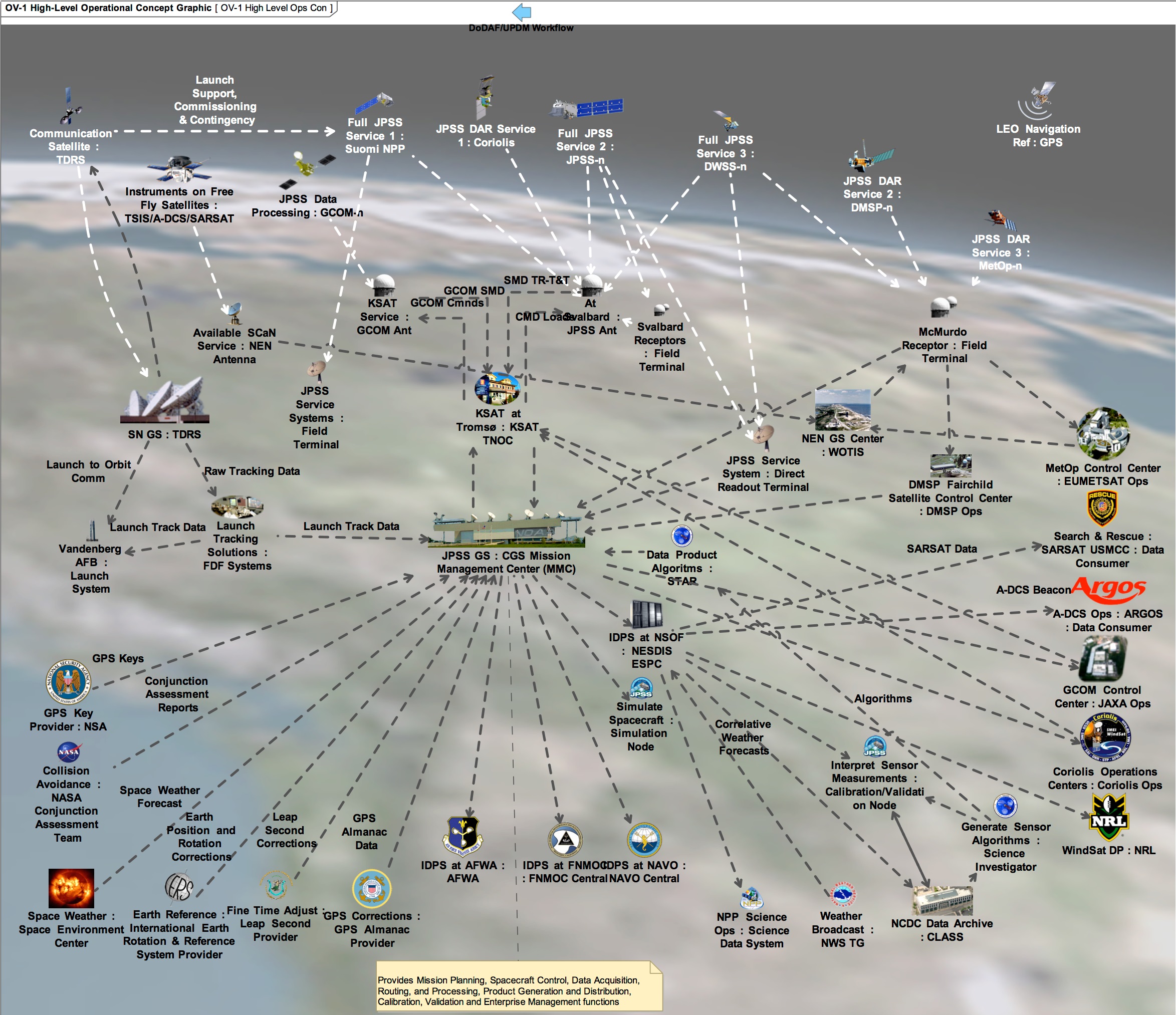
The Command, Control and Communications Segment facilitates all mission planning and management aspects such as antenna resource scheduling, satellite day-to-day operations, data relay and engineering support. Fifteen global ground stations are called up to receive JPSS data and quickly relay it to four U.S. data processing centers from where products are delivered to the Weather Centrals in under 30 minutes from reception. The Mission Management Center provides the tools needed to manage the JPSS missions via software-based mission planning capabilities.
The Interface Data Processing Segment hosts symmetric multi-processing computers designed to deal with the vast amounts of data generated by JPSS and process raw data received from ground stations into Environmental Data Records for distribution. Field Terminals are deployed worldwide via fixed and mobile receiver to receive and process the continuous broadcasts of JPSS and provide products in near real-time for use in military and scientific applications.
