
InSight Spacecraft Overview
The Mars InSight mission leverages the architecture of the successful Mars Phoenix lander mission of 2007/08, re-using the overall structure and systems design of Phoenix for cost and risk reduction through the use of components that have already proven they can operate on a Mars lander system. The lander structure itself goes back to the canceled Mars Surveyor 2001 lander which was re-purposed for the Phoenix mission after being kept in a clean room by Lockheed Martin.
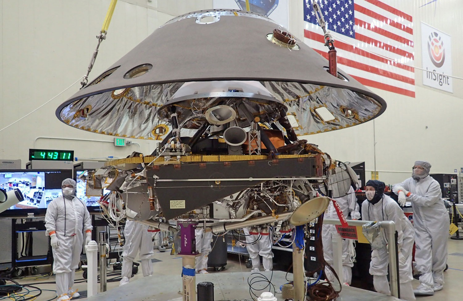
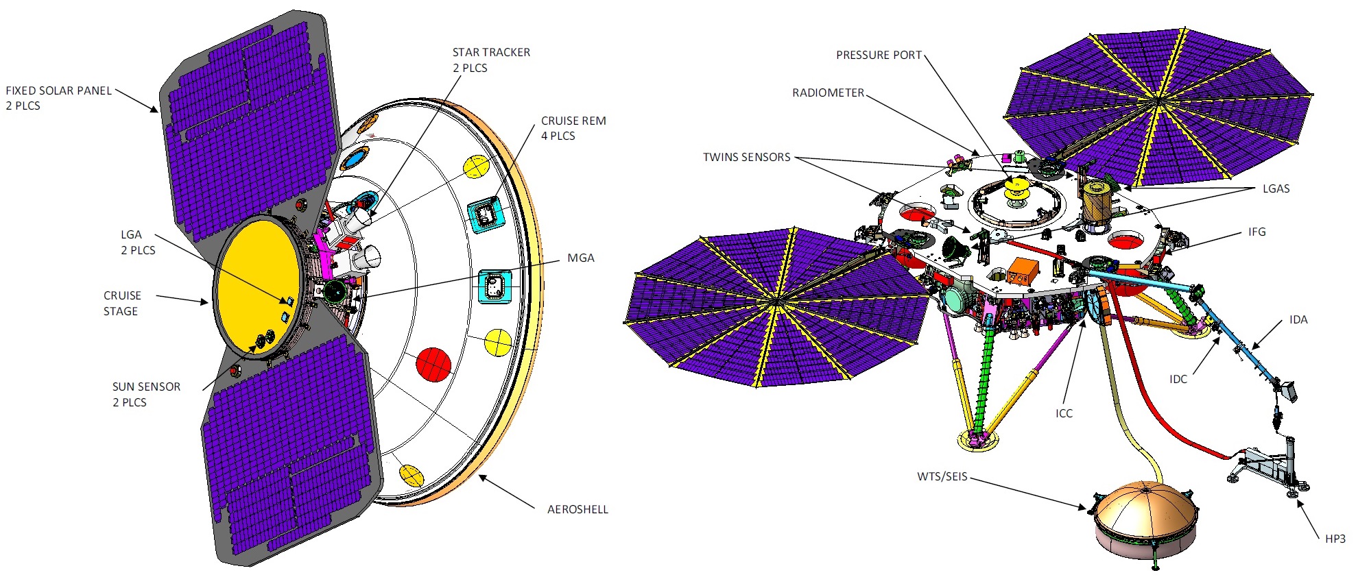
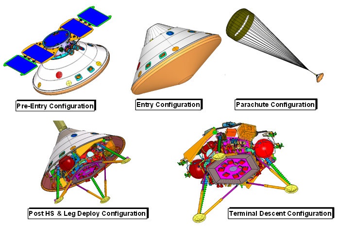
The InSight Spacecraft comprises three principal components: the Cruise Stage provides support during the six-month interplanetary cruise phase from Earth to shortly before entry into the Martian Atmosphere, the EDL (Entry, Descent & Landing) system comprises protective elements like the aeroshell (w/ parachute) and heat shield needed during atmospheric entry, and the Lander itself, designed to touch down on the surface of Mars and deploy its scientific instrument suite for a two-year primary mission. Lockheed Martin is responsible for all elements of the spacecraft.

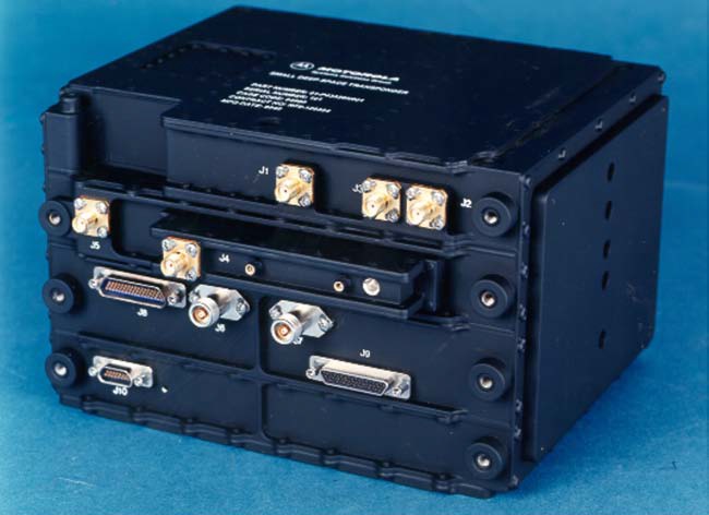
Only few changes have been made for the platform system between Phoenix and InSight, including the replacement of obsolete parts with available hardware, additional provisions to increase reliability, the relocation of a Small-Deep Space Transponder from the Cruise Stage to the Lander, and some modifications to the craft’s avionics to use modern-day components. Operationally, InSight is facing a number of changes compared to Phoenix including a greater mass at the entry point into the Martian atmosphere, a higher entry speed, and a higher-altitude landing location – creating higher demands on the EDL system and leveraging margins identified in post-landing analysis performed for Phoenix.
All in all, InSight has a launch mass of no more than 727 Kilograms including 360 Kilograms for the Lander itself. The InSight Cruise Vehicle measures 2.65 meters in diameter and stands 1.74 meters tall with a solar array span of over three meters; the lander itself has a science deck diameter of 1.56 meters standing between 83 to 108 centimeters above the Martian surface depending on the compression of the shock-absorbing legs at touchdown.
Cruise Stage

The InSight Cruise Stage is nearly identical to that of the Phoenix mission and is tasked with shepherding the lander from Earth to Mars – delivering electrical power, communications with Earth, and precise navigation capability during the six-month interplanetary flight phase. It weighs approximately 80 Kilograms and is attached to the parachute cone of the InSight spacecraft which itself builds the structural backbone for the launch and entry phase as it transfers loads from the booster and parachute into the lander structure.
The Cruise Stage consists of a central cylinder on the outside of which two rigid solar panels are installed to generate power during the interplanetary cruise while the interior of the cylinder provides mounting structures for the various Cruise Stage avionics and communication antennas. On the underside of the central cylinder of the Cruise Stage resides the launch vehicle adapter that connects the spacecraft to the Atlas V launch vehicle while the upper end features the structural interface to the parachute cone holding the InSight lander itself, requiring the Cruise Stage to serve as the primary load carrying element between the booster and the lander.
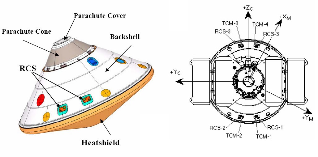
Aeroshell & Parachute
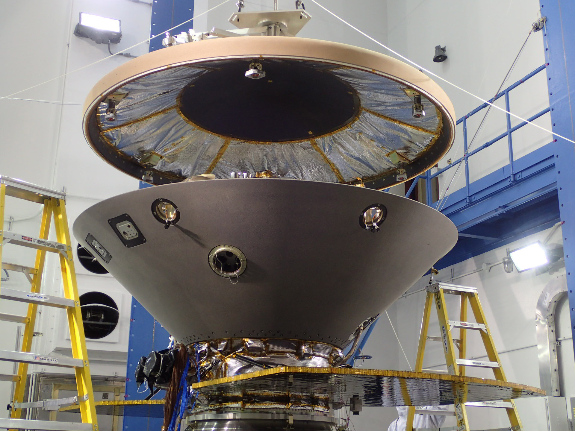
The InSight Aeroshell is essentially a carbon copy of the system used for Phoenix, comprising the 110-Kilogram backshell and 62-Kilogram heat shield to protect the lander during interplanetary cruise and the critical Entry, Descent & Landing Phase.
The backshell facilitates the mounting structure for the Cruise Stage and contains the parachute and its deployment system while the Heat Shield on the base of the vehicle facilitates the thermal protection system needed during atmospheric entry to protect the lander until the craft has slowed well below subsonic speeds.
The backshell is 2.637 meters in diameter and made of an aluminum honeycomb structure sandwiched between graphite-epoxy face sheets and houses the Parachute Support Compartment. The backshell uses the Lockheed SLA-561S Heat Shield Material to protect the inside of the shell from turbulent plasma and heated gases of re-entry.
The InSight Aeroshell has a 70-degree half-cone geometry design with extensive heritage going all the way back to the Viking missions of the 1970s. Its overall size matches that of Phoenix and the MER missions but is smaller than the 3.54-meter Viking and 4.5m MSL aeroshell.
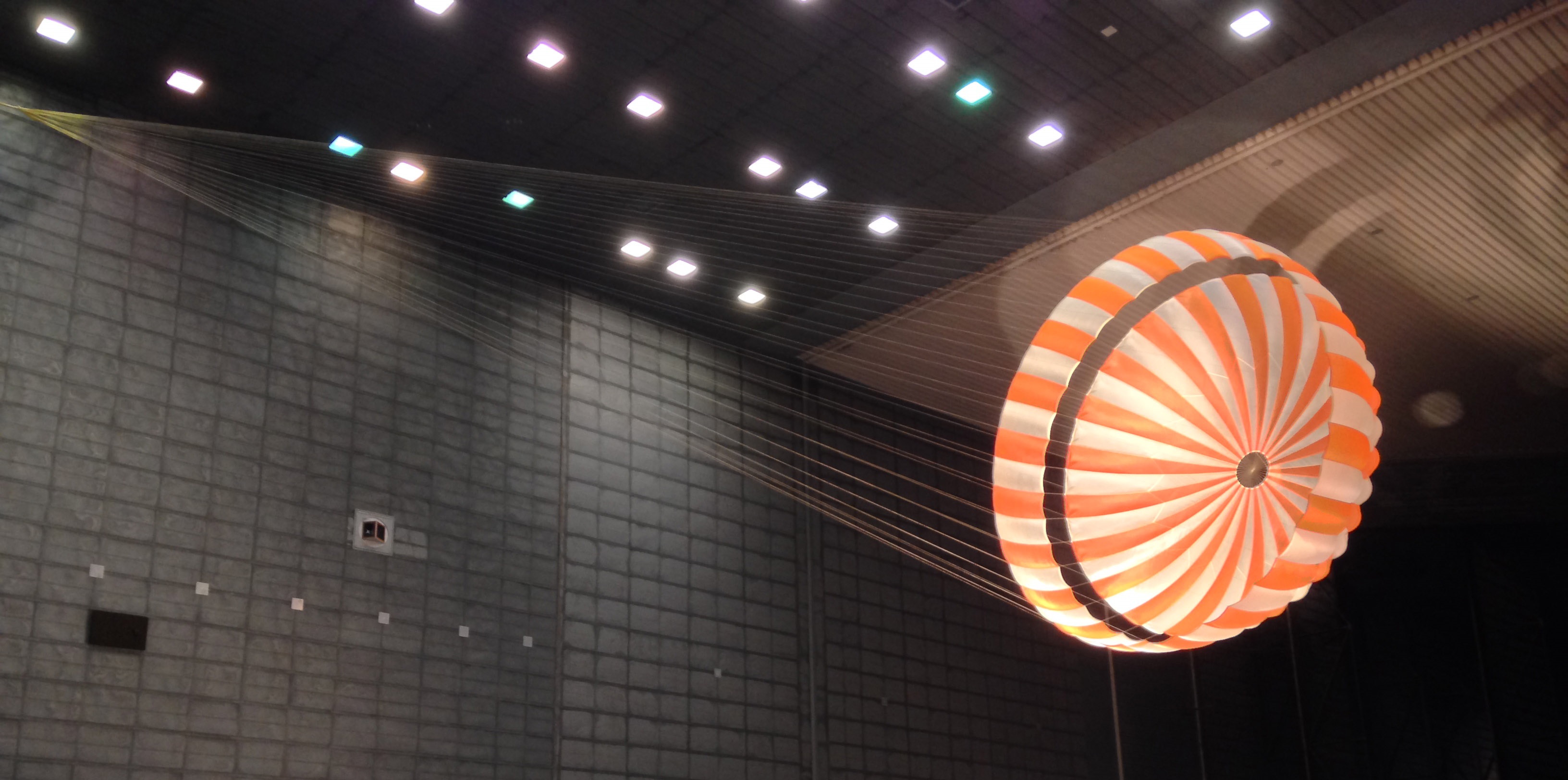
InSight employs a mortar-deployed parachute very similar to that of Phoenix, the only changes being a switch in suspension line material to accommodate a larger inflation load expected on the parachute due to different spacecraft mass and trajectory. The chute resides within a cylindrical support compartment responsible for holding and deploying the parachute and transferring loads from the chute to the rest of the vehicle via three tripod-type struts that connect the lander’s deck to the parachute cone.
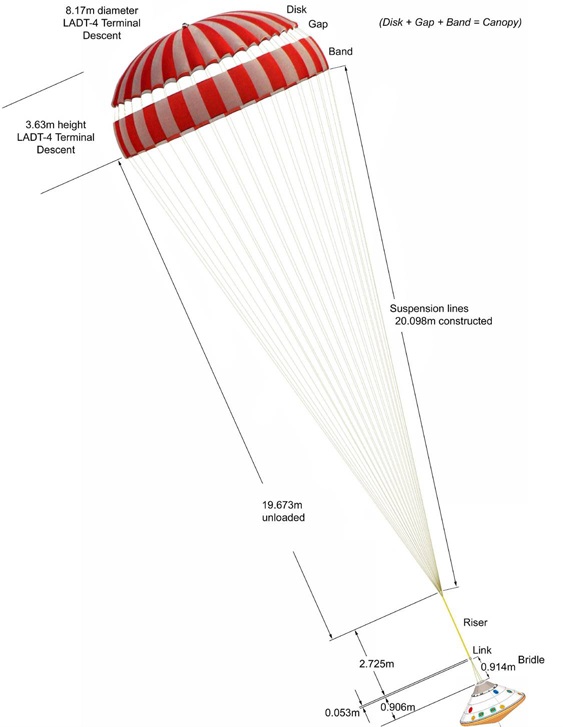
The parachute system used for InSight is a disk-gap-band type parachute employing a central disk and a cylindrical band, separated by a gap. The chute is 11.73 meters in diameter with 20.1-meter long suspension lines and its mortar deployer ejects the chute at a speed of 38 meters per second relative to the spacecraft to create an initial line stretch 0.75 seconds after mortar fire.
Chute deployment is commanded based on an accelerometer trigger programmed to initiate the deployment at a dynamic pressure around 430 N/m² corresponding to a speed of Mach 1.7 and an altitude of 10.5 Kilometers over MOLA.
The parachute disk itself is 8.6 meters in diameter with an 0.8-meter vent at the top of the chute; the gap between the disk and band is 0.5 meters high and the fabric band covers 1.4 meters – creating a 109.4m² reference area. The suspension lines connect to the backshell through a 2.73-meter long riser and 0.91-meter bridle.
Changes from the Phoenix chute to InSight arise from the maximum entry mass of 625 Kilograms for InSight vs. 590 kg for Phoenix which, combined with trajectory and atmospheric factors, leads to a 15% increase in parachute inflation load. To accommodate the increased peak inflation load, InSight’s suspension lines switched from Kevlar used by Phoenix to Technora that was also used by the Mars Science Laboratory Rover while the Bridle Legs have been made stronger by increasing their diameter. Another change, arising from the slightly thicker lines, is an increase in packing density within the parachute compartment.
The heat shield protecting the InSight Lander during the hypersonic phase of the entry process into the Martian atmosphere is very similar to that used by Phoenix which in turn leverages materials and manufacturing techniques from the Mars Pathfinder mission and the two Mars Exploration Rovers. The only difference to the heat shield used on Phoenix is an increase in the ablator material thickness to account for a higher degree of dust abrasion given InSight’s landing around the time of dust storm season whereas Phoenix was facing a calmer atmosphere.

The 2.65-meter diameter, spherically-blunted 70-degree half-angle cone makes use of Lockheed Martin’s Super Lightweight Ablator (SLA) 561V Thermal Protection System (TPS) material. The principle behind an ablative heat shield is protecting the spacecraft structure by allowing the heat shield material to slowly burn away in order to create a boundary layer of colder gas in between the extremely hot shockwave layer of crushed gas and plasma and the spacecraft structure in order to protect against all forms of heat flux.
The processes occurring at the heat shield material include a charring, melting and sublimation on the one hand and pyrolysis on the other. Pyrolysis creates the product gases that are blowing outward and create the desired blockage of convective and catalytic heat flux. Radiative heat flux is reduced by introducing carbon compounds into the boundary layer gas which make it optically opaque.
SLA-561V has been used for every Mars mission to date with the exception of the Mars Science Laboratory; the material begins significant ablation at a heat flux of 110 W/cm² and tolerates heat fluxes up to 300 W/cm². Assembly of the heat shield starts out with a fiberglass-phenolic honeycomb bonded to the inner aeroshell structure and then packed with the ablative material in a manual and labor-intensive process.
The only change made on the heat shield from Phoenix to InSight is a “nominal increase in TPS design thickness” – referring to a slightly thicker heat shield to account for greater dust erosion experienced by InSight. The delay from the 2016 to the 2018 launch window caused a decrease in inertial entry velocity from 6.1 to 5.6 Kilometers per second, putting it in the same ballpark as Phoenix, through the craft’s mass is slightly higher than Phoenix.
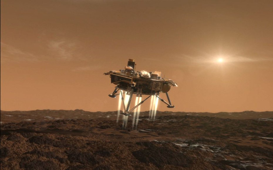
The heat shield separates from the lander and backshell approximately 15 seconds after parachute deployment when speed will have decreased to around 120 meters per second. The aeroshell’s mission ends around 980 meters above the Martian surface when the InSight lander detaches to begin its propulsive landing maneuver with 12 pulsed landing thrusters.
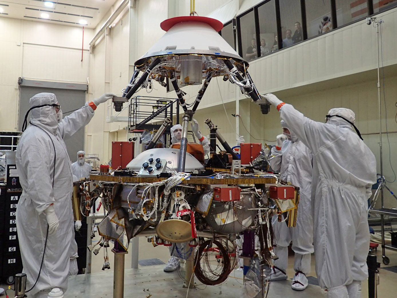
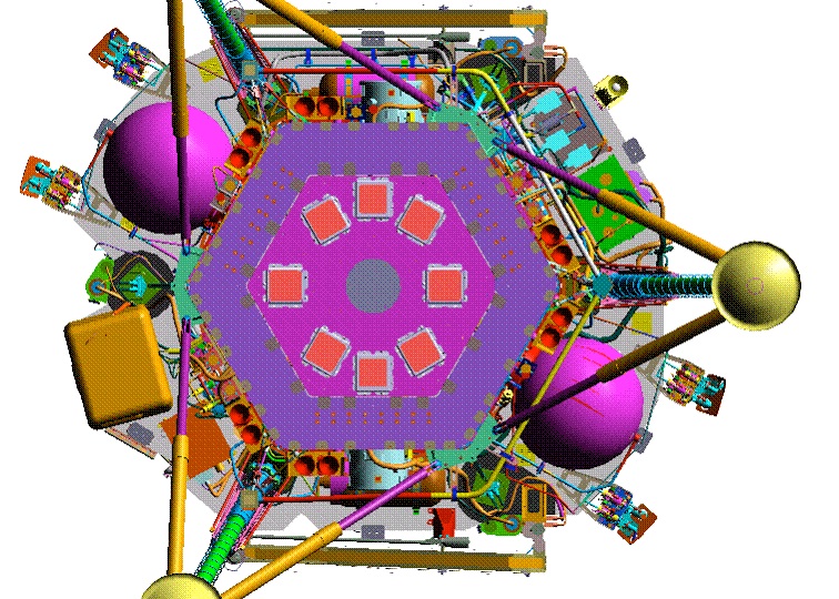
Lander Structure
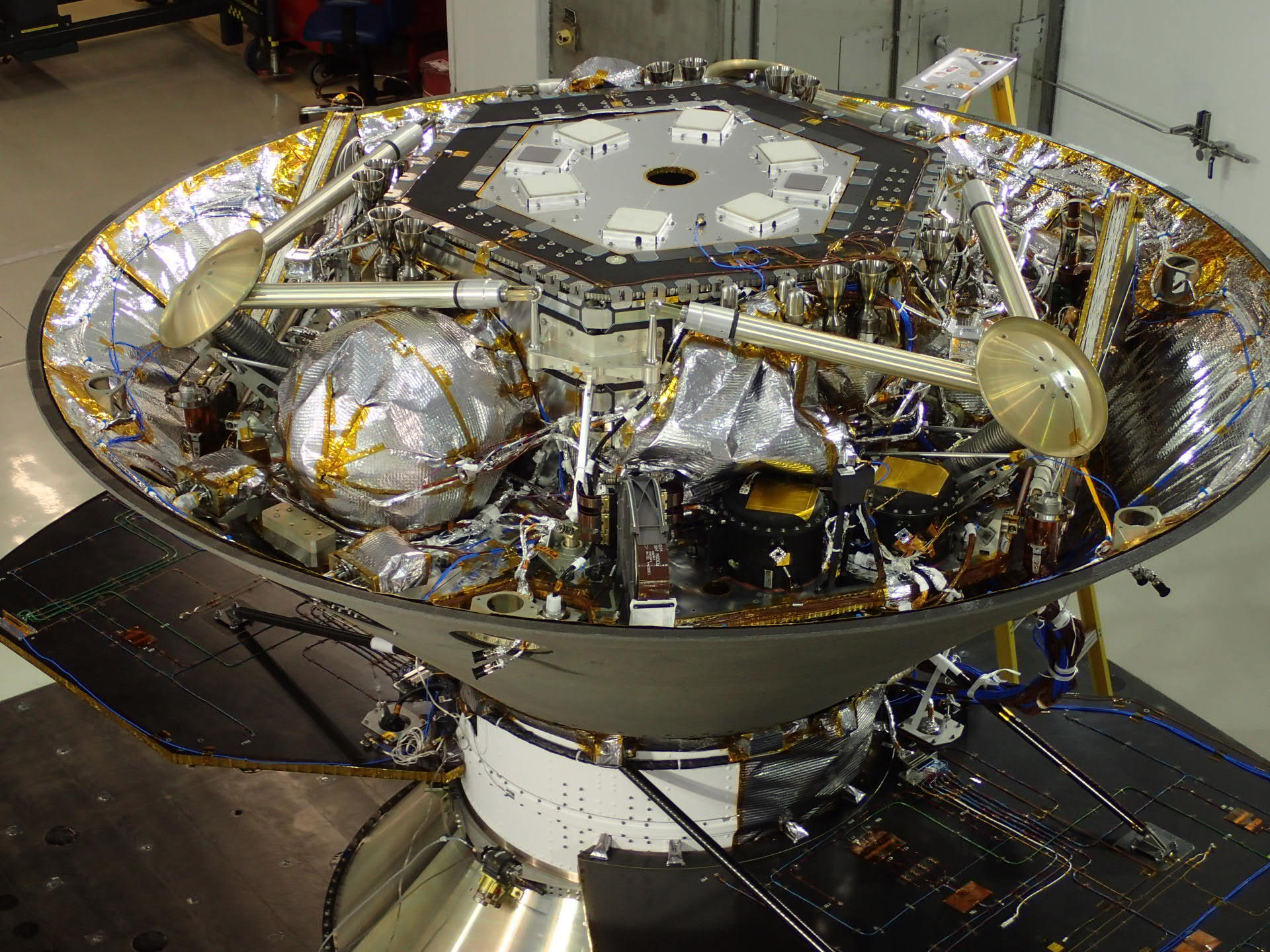
The InSight Lander is identical to Phoenix from a structural point of view – comprising a deck as the primary structural element from which all other elements of the lander extend. It provides the mounting surfaces for all lander electronics boxes, the propellant tanks, thrusters and the landing legs. As the central load-carrying element of the InSight Lander, the deck comprises a honeycomb-composite interior and aluminum external panels.
The Lander Deck doubles as a thermal protection element since its honeycomb structure has a low thermal conductivity and can thus protect the various electronics boxes installed underneath it – effectively reducing power requirements for heaters, especially during cold nights on the red planet. Thermal control during the lengthy cruise phase from Earth faces the exact opposite since InSight is enclosed in its aeroshell without an ability to radiate heat. For this flight phase, the lander relies on heat pipes to transport heat away from the electronics and to colder parts of the spacecraft to avoid temperatures exceeding their upper threshold.
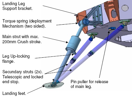
One of the most critical structural elements on the InSight lander is its landing system comprising three inverted-tripod type legs with crushable absorbers to provide soft-landing capability. The inverted tripod configuration has flown successfully on various missions and employs a primary leg extending from the main deck of the lander and two secondary supports connecting the base of the deck directly to the foot pad. This design reduces ground clearance but helps with shock absorption.
The legs are installed on hinges, allowing them to be stowed under the deck, secured by a pin-pull release mechanism. Upon release, a torque-spring within the primary leg will move it and the secondary supports into their deployed position with an up-locking mechanism rigidizing the primary leg in its fully deployed position with zero tolerance along the deployment mechanism. Shock absorption is accomplished with an aluminum honeycomb crush core that functions in the form of a compressible cartridge between an inner and outer cylinder to serve as a one-use shock absorber.
Because no active hazard-avoidance is used by InSight, the legs must be capable of supporting worst-case landing scenarios like 16° slope and up to 40cm rocks in combination.
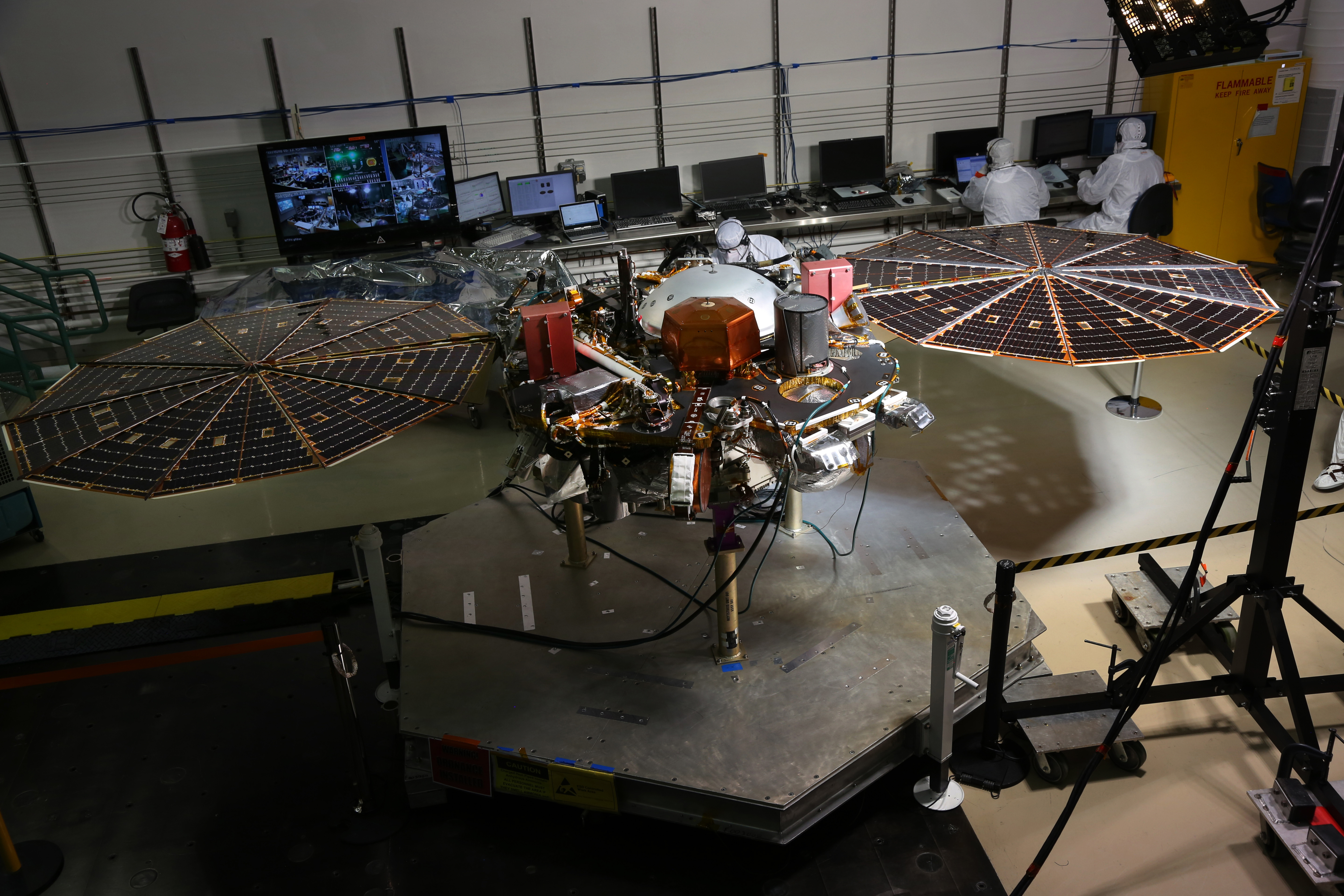
Electric Power System
The InSight spacecraft carries two sets of solar arrays for power generation, one installed on the vehicle’s cruise stage to deliver power during the interplanetary transit and one on the lander to deliver power during the landed mission of at least one Mars Year (two Earth years). As with many elements of the InSight mission, the EPS is similar in architecture to the Phoenix mission of 2008; however, some elements have been changed like the type of solar cell used on the Cruise Stage and the size of the lander solar arrays.
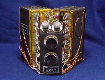
InSight makes use of a unified power system with only one set of batteries across the spacecraft, located aboard the lander and charged either from the Cruise Stage solar generator during cruise or the surface platform’s arrays. The Li-Ion battery pack flown is identical to that of Phoenix, weighing in at 17.8 Kilograms and comprising two parallel strings of eight battery cells for a total capacity of 50 Amp-hours (62 Ah demonstrated by Phoenix).
Rated for a four-year design life, the battery operates between 24 and 32.8 Volts with a nominal setpoint at 28V. The InSight battery went through a pre-flight testing program subjecting it to an operational temperature range of -30 to +35°C and validating its capacity at thermal extremes.
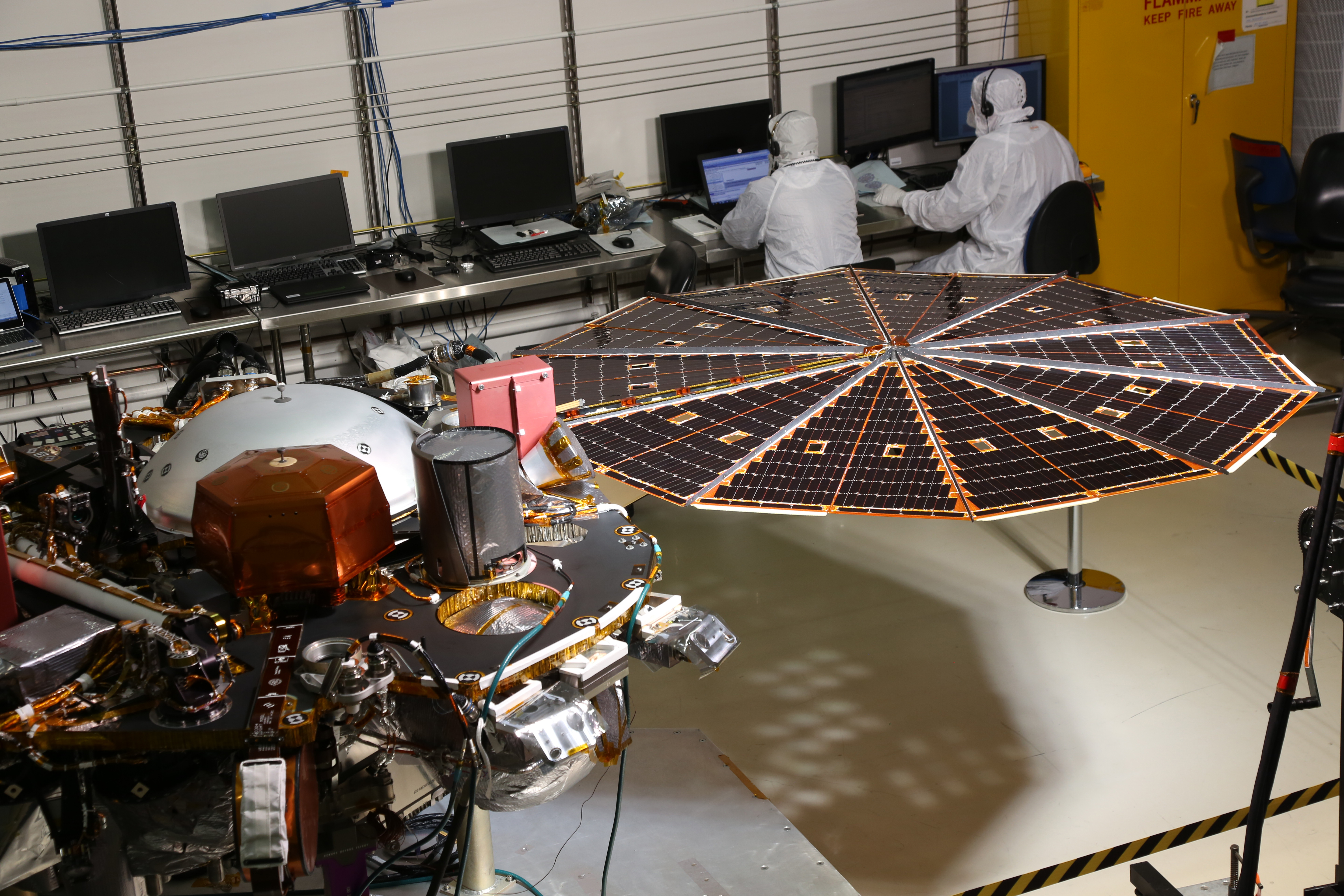
The two surface platform solar arrays were provided by Orbital ATK based on the company’s flexible UltraFlex design that has flown successfully on the Phoenix mission as well as several missions of the company’s Cygnus cargo spacecraft. The motor-driven arrays will unfurl to their circular shape after InSight lands to reach a diameter of 2.15 meters, growing by five centimeters compared to Phoenix.
Another change to Phoenix is the upgrade from triple-junction solar cells to high-aspect ratio ZTJ solar cell technology of SolAero with a 29.5% efficiency at beginning of life, making them the most efficient solar arrays in terms of watt-per-kg ratio ever flown on an interplanetary mission. The two circular solar arrays generate up to 700 Watts of electrical power at the start of the mission and are rated to withstand Mars winds of up to 75 meters per second.
Propulsion & Attitude Actuation
The Propulsion Subsystem of the InSight Lander is identical to that flown on Phoenix – featuring a total of 20 thrusters broken down in three different groups: 1) Reaction Control System thrusters with a nominal thrust of 4.5 Newtons, 2) Trajectory Correction Thrusters operating at 22 Newtons and 3) Pulsed Landing Thrusters generating 293 Newtons of thrust for attitude control and velocity reduction during the Mars Landing Maneuver. All thrusters are fed from two central tanks containing ~65 Kilograms of usable propellant.
All thrusters use the decomposition of Hydrazine monopropellant over a metallic catalyst bed to create high-pressure gas that can be expelled through a nozzle to generate thrust. The system operates in blowdown mode without in-flight pressurization, starting out at a pressure of 21 bar provided by Helium ground pressurization.
Over the course of the mission, as propellant is expended, tank and feed pressures will decline and cause engine thrust and specific impulse to decrease – requiring detailed analysis of the thruster response to decreasing inlet pressure to ensure accurate maneuvering over the course of the mission.
InSight has four Rocket Engine Modules (REMs) used during the Cruise Phase and to set the vehicle’s orientation for atmospheric entry – each comprises one Reaction Control System (RCS) and Trajectory Correction Maneuver (TCM) thruster. All REMs are installed on the InSight lander deck and scarfed through the backshell via cut-outs, avoiding the complexity of adding a separate propulsion system for cruise control which would have come with a significant mass penalty.
All TCM thrusters lie in the -X direction of the spacecraft coordinate system to operate for large delta-v burns and due to the scarfed nozzles, their effective thrust direction is offset from the nozzle direction by 2.5°. The RCS thrusters are arranged such that each has a component of thrust in all three spacecraft axes; the thrust directions are balanced out along the Y and Z axes but not on the X-axis causing some delta-v to be impacted on the +X axis with every RCS burn.
The Attitude Control System of InSight is operated in a three-axis stabilized mode using the RCS thrusters for attitude corrections, mainly caused by external perturbations like solar pressure or dust particle hits during the coast phase. Attitude variations are allowed within a set of deadbanding boundaries defined by the pointing requirements of the solar panels and comm antennas as well as thermal constraints.
Whenever the spacecraft controller, based on inputs from the Star Trackers & IMU, detects the attitude reaching the deadband limit, the thrusters will be commanded to fire to return the spacecraft into a nominal attitude. Deadbanding constraints will vary in the different mission phases based on the requirements for the Sun-Earth-Probe angle and range to sun and Earth.
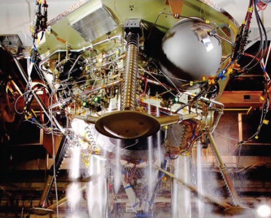
The 12 Terminal Descent Thrusters are installed around the bottom panel of the deck and are tasked with delivering InSight from the point of separation from the backshell and parachute to a gentle landing on the Martian surface at a speed of less than 3 meters per second.
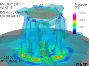
They are operated in pulse mode to arrest the craft’s horizontal and vertical velocity and also keep it in the proper orientation for landing, achieved through differential pulsing of the thrusters to actively control the pitch, yaw and roll of the lander.
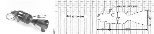
Chosen for the Terminal Descent Thruster was the Aerojet Rocketdyne MR-107N, capable of providing a nominal thrust of 170 Newtons with a range of 109 to 296 Newtons. With the 12 engines at nominal throttle, InSight has a total thrust of 3,516 Newtons (capable of decelerating the craft at 2.65 Gs).
MR-107N operates at a propellant feed pressure of 8.2 to 27.8 bar and a chamber pressure of 4.2 to 11.2 bar to create a specific impulse of 229 to 232 seconds. The engine ingests 49 to 131 grams of fuel per second depending on the thrust setting. It has a expansion ratio of 20.7. MR-107N weighs 740 grams, measuring 22 centimeters in length and 6.6 centimeters in diameter. It uses a Moog Single Seat Valve. The engine is certified for nearly 1,500 duty cycles.
The TCM Thrusters, Aerojet Rocketdyne MR-106 engines, deliver 22-Newtons of thrust with an operational range of 11.6 to 30.7 Newtons operating at a feed pressure of 6.9 to 24.1 bar and chamber pressure of 4.5 to 12.4 bar.

The thruster provides a specific impulse of 229 to 235 seconds. It has an expansion ratio of 60 and consumes 5.0 to 13.1 grams of propellant per second. MR-106 weighs 635 grams with a length of 18.2 centimeters and a nozzle diameter of 3.4 centimeters. The 22N thruster uses a Dual Seat prop valve. It is certified for more than 50,000 duty cycles and long firings of up to 2,000 seconds as well as a cumulative burn time of 4,670 seconds.
For smaller attitude control maneuvers, InSight has four MR-103 thrusters each providing a low thrust of 1 Newton with an operational range of 0.22 to 1.02 Newtons. MR-103 operates at a propellant feed pressure of 6.2 to 27.6 bar and a chamber pressure of 5.9 to 23.4 bar as the engine uses 0.09 to 0.5 grams of Hydrazine per second.
The engine has an expansion ratio of 100 being 14.6 centimeters long with a mass of 330 grams and a diameter of 3.4 centimeters. A Dual Seat Valve is also used on this engine that provides a specific impulse of 209 to 224 seconds. MR-103 is certified for 275,000 duty cycles and a cumulative burn time of 111 hours along with a single firing certification of 5,000 seconds.
Attitude Determination
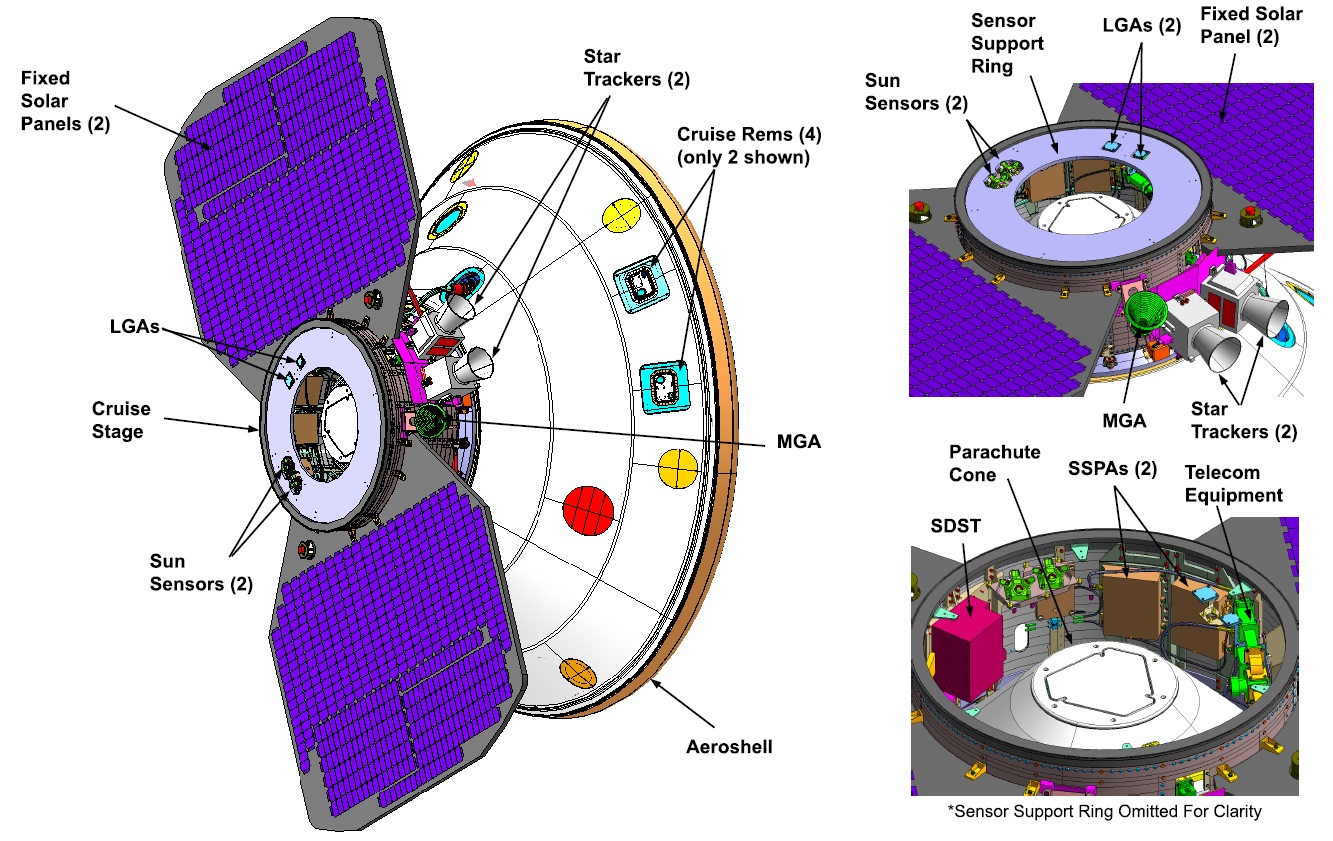
The InSight Attitude Control System consists of two Star Trackers mounted external to the Cruise Stage, a Miniature Inertial Measurement Unit (MIMU) and Analog Sun Sensors installed atop the Cruise Stage to have the same boresight as the fixed solar panels. The primary means of attitude determination is the Star Tracker-MIMU combination with the Star Trackers in charge of delivering precise attitude quarternions and the MIMU delivering data for updating the spacecraft state in between ST data.
The Star Trackers are the same as used on the Mars Odyssey mission and each has a 16.4 x 16.4-degree field of view across which it captures imagery of the star-filled sky. These images are then put through an onboard algorithm that contains a catalog of bright star constellations to allow for a precise calculation of the craft’s three-axis orientation in space.

MIMU data is used to propagate the vehicle orientation in between ST updates and for the initial acquisition phase during which body rates are reduced for Star Tracker readings. The two Analog Sun Sensors installed atop the Cruise Stage are used as backup system in case of safe mode events to ensure the power-generating solar panel points to the solar vector which also ensures the Low Gain Antenna boresight is sufficiently aligned with Earth.
The attitude profile chosen for the Cruise Phase of the InSight mission arises from the need of having the solar panels oriented normal to the solar vector and for the Low and Medium Gain Antennas to be pointed sufficiently close to Earth. To satisfy these constrains, the spacecraft -X axis is pointed between the direction of Earth and the direction of the sun, also meeting thermal requirements and keeping the Star Trackers pointed away from the sun.
During the early Cruise Phase of the mission (until around L+70 days), InSight points the -X axis 50 degrees off sun in order to meet thermal requirements while still close to the sun. In the late Cruise Phase, communications switch from the Low- to the Medium Gain Antenna and the -X axis points directly to the sun, keeping the MGA aligned with the Sun-Earth Plane.
Throughout its Cruise Phase, InSight remains in active three-axis control – unlike the Mars Science Laboratory that used spin stabilization for passive flight phases and only transitioned into three-axis control for major Trajectory Correction Maneuvers. InSight’s orientation will be allowed to vary within a set of deadband conditions that are defined for every stage of the mission by the telecom, power and thermal requirements. The spacecraft controller will command thruster firings each time the measured attitude reaches one side of the defined deadbands.
Deadbands for the Early Cruise Phase are 10 degrees around the X & Y axes and 7.5° on the Z-axis, reducing to 4 degrees for all three body axes for the later cruise. One undesired side effect of active three-axis stabilization via thruster control is a change in velocity imparted on the vehicle every time a thruster fires – causing uncertainty in the trajectory which has to be modeled accordingly in order to ensure the spacecraft hits its Entry Interface point at Mars with high precision for an on-target landing. This is realized through a Small Force File created from spacecraft telemetry from every thruster firing and input into the trajectory simulator.
With the separation of the Cruise Stage seven minutes before re-entry, the InSight spacecraft solely relies on its MIMU for attitude propagation, rate measurement and the deceleration trigger for the critical parachute deployment event. Two redundant MIMUs reside on opposite sides of the lander, each comprising three QFLEX accelerometers for linear acceleration measurements along the three body axes and three Honeywell ring-laser gyros for angular rotation measurement.
The MIMU outputs data at 200 Hz including the accumulated linear velocity change and the accumulated angle change in three Cartesian axes. After digitization of the raw data, the MIMU achieves a delta-v resolution of 2.7 mm/sec at a noise level of under 0.08 mm/sec and angular data is delivered with a resolution of 0.011 deg/sec.
Landing Radar
The Terminal Descent Phase of the InSight EDL maneuver is guided by a combination of readings from the Miniature Inertial Measurement Units and a Landing Doppler Radar installed on the base of the lander to provide precise measurements of relative velocity in the vertical and horizontal directions. Data from the sensors will be employed to slow the lander to a speed of around 2.4 meters per second for touchdown and keep it in the proper orientation during final descent for simultaneous contact on all three legs.
The Honeywell-built Landing Radar is of Mars Polar Lander / MER heritage and combines the functions of a broadband altimeter and velocimeter. A total of eight antenna patches are installed on the base of the lander deck and operating in pairs (one for the transmission of pulses and one for the reception of echoes). This allows four radar beams to be created – one nadir-pointed beam for altitude and velocity measurements and three electronically-steered side-pointed beams for velocity measurements in the horizontal domain. The side beams are pointed 30 degrees off-nadir.

The use of separate antennas for the transmit and receive signal chains avoids the need for a high-speed switch to alternate between transmit/receive events and allows the lander to detect echoes much earlier in time when at low altitude during final decent. The radar operates at a Ka-Band frequency of 4.3 GHz, sending bi-phase modulated pulses with a 100-millisecond measurement period and a transmit power of 1 Watt. The pulse width and modulation is actively adjusted based on the vehicle’s altitude to achieve the desired signal strength and accuracy – supporting pulse repetition frequencies of 14 to 400 kHz and a Doppler sampling range of 3.24 or 6.0 kHz.
During each measurement cycle, the radar obtains one altitude measurement through the nadir antenna for altitude-above-ground and vertical speed measurements and, based on commanding from the spacecraft, obtain a range-gated Doppler measurement from one or more of the outer antennas. Each measurement cycle creates a data packet containing the altitude reading, a Fast Fourier Transform of the frequency spectrum and a validity flag.
The radar is capable for altitude measurements between 0 and 2,438 meters; activation is expected at an altitude of 12 Kilometers and search mode at 7.2 Kilometers with first acquisition required by an altitude of 1,650 meters.
Data Handling & Telecommunications
The avionics system of the InSight mission has undergone the most significant changes compared to Phoenix. Although Phoenix flew less than a decade before InSight, its basis was the 2001 Mars Surveyor Lander which was designed in the 1990s. As is typical for space-rated devices, they are typically around a decade behind consumer products – meaning Phoenix flew with computing technology from the early 1990s. Therefore, there was desire to bring InSight to the current state of interplanetary avionics systems – not only for its computing needs but also to ensure proper compatibility with the current ground infrastructure in use for Mars missions.
The avionics modernization process for InSight kept with the mission’s overall design mantra of risk reduction through heritage, flying avionics packages that were used on the Juno Mission to explore Jupiter, the GRAIL twins studying the Moon’s interior and the Mars MAVEN mission probing the Martian atmosphere.
Juno, MAVEN, GRAIL and presumably InSight (still subject to confirmation), all use the RAD-750 Central Processing Board that is a single-card computer manufactured by BAE Systems in Manassas, Va.
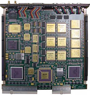
The processor can endure radiation doses that are a million times more extreme than what is considered fatal to humans. The RAD750 CPU itself can tolerate 200,000 to 1,000,000 rads. Also, RAD750 will not suffer more than one event requiring interventions from Earth over a 15-year period. “The RAD750 card is designed to accommodate all those single event effects and survive them. The ultimate goal is one upset is allowed in 15 years. An upset means an intervention from Earth — one ‘blue screen of death’ in 15 years. We typically have contracts that (specify) that,” said Vic Scuderi BAE Business Manager.
RAD-750 was released in 2001 and made its first launch in 2005 aboard the Deep Impact Spacecraft. The CPU has 10.4 million transistors. The RAD750 processors operate at up to 200 megahertz, processing at 400 MIPS. The CPU has an L1 cache memory of 2 x 32KB (instruction + data) – to improve performance, multiple 1MB L2 cache modules can be implemented depending on mission requirements. RAD750 operates at temperatures of -55°C to 125°C with a power consumption of 10 Watts. The standard RAD750 system can tolerate 100,000rads.
The Data Handling System receives data from the payload and can send commands to the payloads as part of stored operational sequences. Data from the navigation sensors are also processed by the Data Handling Systems that in turn command the attitude control system and propulsion systems of the vehicle. Housekeeping operations such as the commanding of heaters based on temp sensor data and power management is also accomplished by the computer system.
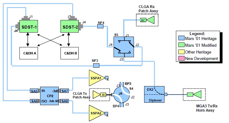
The Cruise Telecommunications System comprises fully redundant X-Band Small Deep Space Transponders (SDSTs) and 15-Watt Solid State Power Amplifiers (SSPAs), residing within the Cruise Stage structural ring and connected to a fixed, dual-frequency Medium Gain Antenna and two low-gain patch antennas (one transmit and one receive) operating at 7.152 GHz for uplink and 8.403 GHz for downlink. The maximum X-band downlink rate is 2,100 bits per second (10 bit/s minimum) while uplink rates range from 7.8 to 2,000 bit/s.
Communications during the Entry, Descent and Landing Phase are handled by a 401.586 MHz UHF communications system comprising a wrap-around antenna on the backshell, active from Cruise Stage Separation to backshell separation, and a monopole helix antenna on the lander, active during the Terminal Descent phase. Critical-event data transmitted through UHF will be collected by the Mars Reconnaissance Orbiter and the two MarCO CubeSats for re-transmission to Earth.
On the surface of Mars, InSight will continue to rely on its UHF communications terminal to send housekeeping and science data to the various NASA and ESA Mars Orbiters that double as communications relay points tasked with delivering command sequences from Earth to the surface vehicles and accepting stored science and telemetry data.
One change from the Phoenix mission for InSight is the relocation of one SDST from the Cruise Stage to the lander and the addition of one SSPA inside the lander deck thermal enclosure, coupled to a redundant pair of fixed Medium-Gain Antennas to be used for the RISE radio experiment active throughout the landed mission. This also enables InSight to communicate directly with the Deep Space Network as a backup to the orbiter-based relay system, though at largely reduced data rates.
