
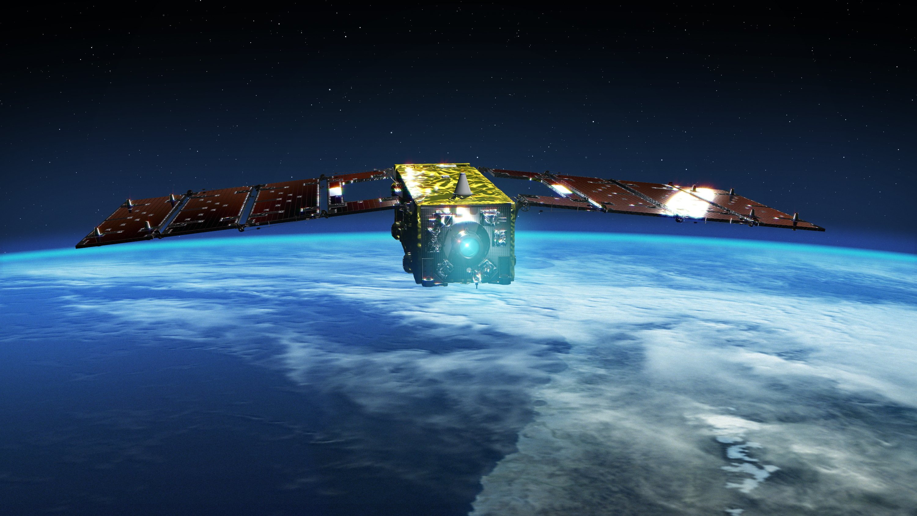
SLATS – Super-Low Altitude Test Satellite
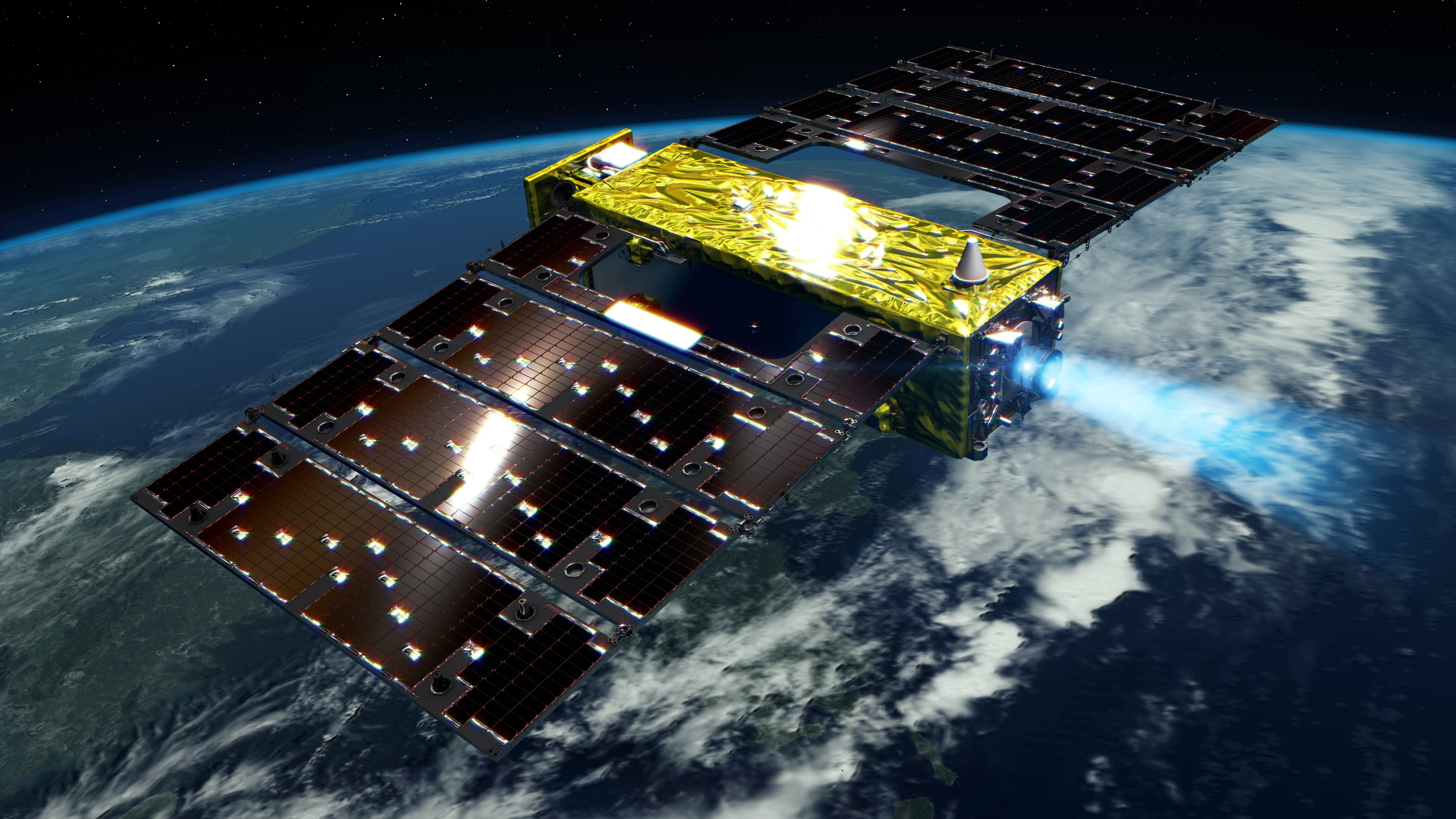
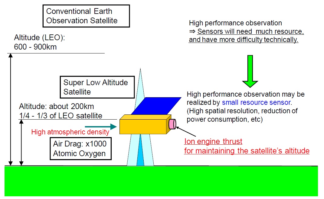
SLATS, the Super Low Altitude Test Satellite, also known under the name Tsubame, is a 400-Kilogram engineering test satellite to demonstrate the feasibility of operating scientific satellites in Extremely Low Earth Orbits where the craft has to actively battle aerodynamic forces to prevent orbital decay. Orbits under 300 Kilometers in altitude are largely undeveloped real estate, but offer great scientific promise for missions studying Earth’s atmosphere and gravitational field; operating imaging satellites closer to planet will also yield improved image resolution.
But operating satellites at orbital altitudes between 180 and 300 Kilometers has to be a careful endeavor, navigating a fine line between staying in orbit and succumbing to drag and re-entering the atmosphere in case orbit maintenance can not be performed correctly for even the shortest time given the air resistance at these super-low altitudes which exceeds that experienced by typical Earth Observation satellites (600km in altitude) by a factor of 1,000.

One satellite that managed to navigate this fine line for an extended period of time was ESA’s GOCE – the Gravity Field and Steady-State Ocean Circulation Explorer that launched in March 2009 and spent the majority of its 4-year & 7-month mission between 235 and 270 Kilometers in altitude to obtain high-precision measurements of Earth’s gravitational field. Other satellites, such as those deployed from the International Space Station, typically remain in operation when crossing through the 300 to 200 Kilometer altitude range, though only fly at these altitudes for so long given the high-drag environment.
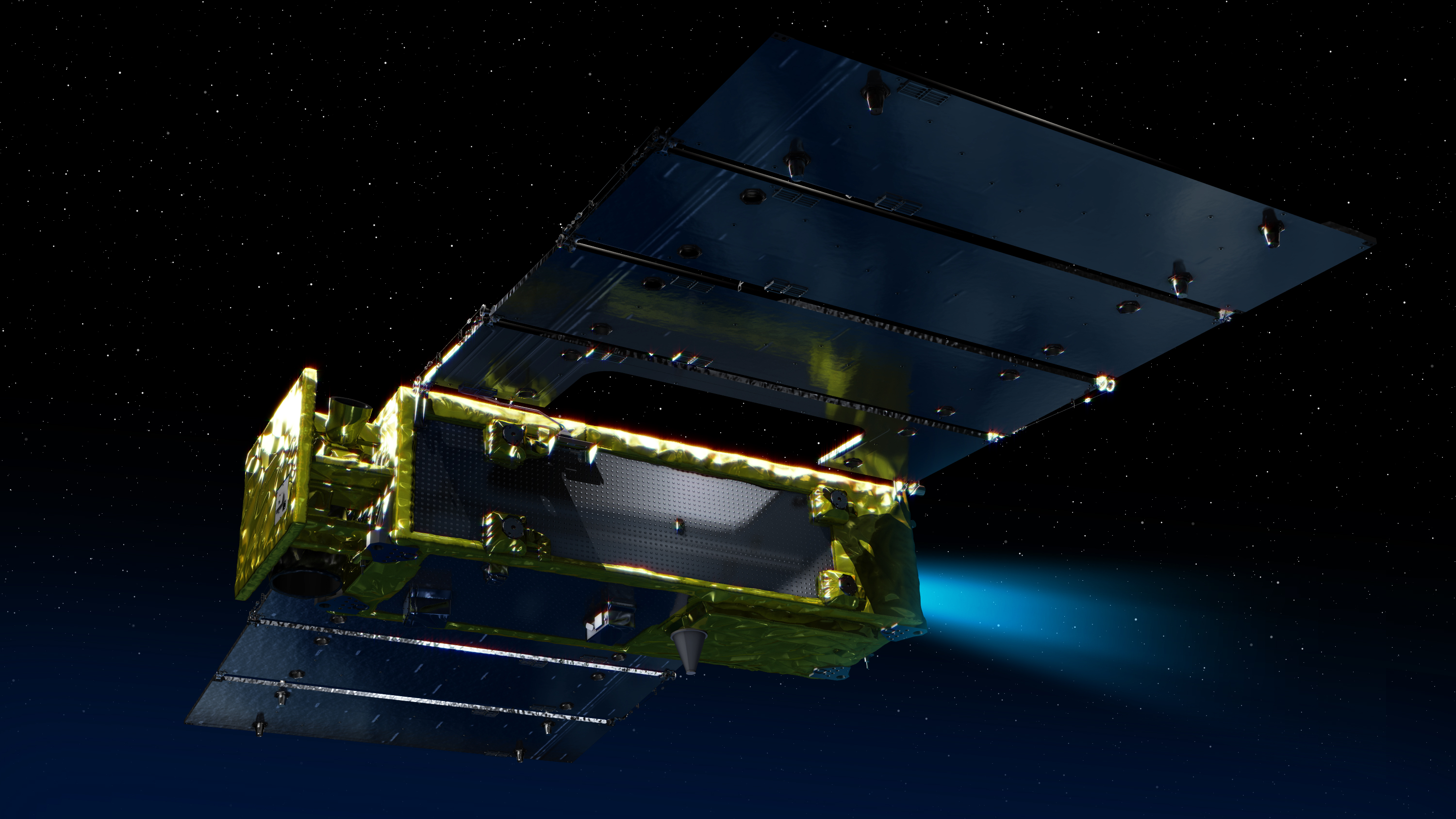
The SLATS satellite hosts a hybrid propulsion system featuring chemical thrusters and ion engines to be able to accomplish fast orbital changes using the traditional thrusters and long thrust phases for drag compensation with the ion engine (also allowing the chemical thruster to serve as backup to lift the satellite out of the denser atmosphere in case the ion engine suffers a temporary outage).
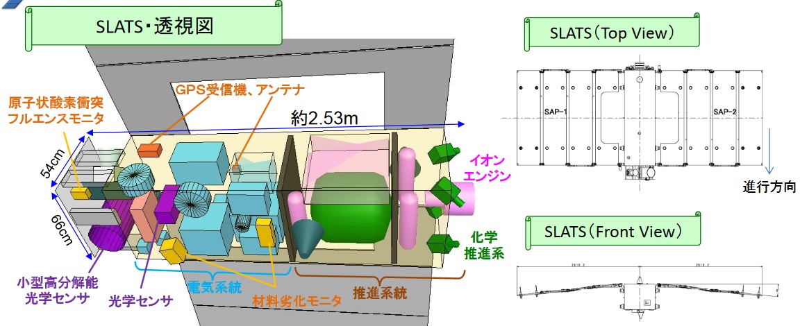
While the primary objective of the mission is the demonstration of super-low altitude flight operations, SLATS also hosts four instruments that are designed to demonstrate the feasibility of science data collection from orbits of this kind: two instruments measuring atomic oxygen – the abundant species at the satellite’s altitude regime, a material degradation experiment to look into the effect of high atomic oxygen influx on different samples, and an optical sensor to test out Earth observation data acquisition from this novel orbital regime.
The three core goals of the SLATS mission are: a) verification of a super low altitude satellite system and the feasibility of ion propulsion for orbit maintenance at altitudes between 180 to 250km, b) measurements of atmospheric density at the satellite’s orbital altitude, and c) in-situ measurement of atomic oxygen and study of the effects of high-density atomic oxygen on the satellite.
SLATS received the nickname Tsubame in a public naming contest in 2014, the Japanese name for the Barn Swallow – a passerine bird with distinct blue color and curved, pointed wings. The mission was originally planned to launch as a secondary payload on the ALOS-2 mission 2014 but was re-manifested to ride into orbit with the GCOM-C1 satellite that slipped from 2016 into late 2017.
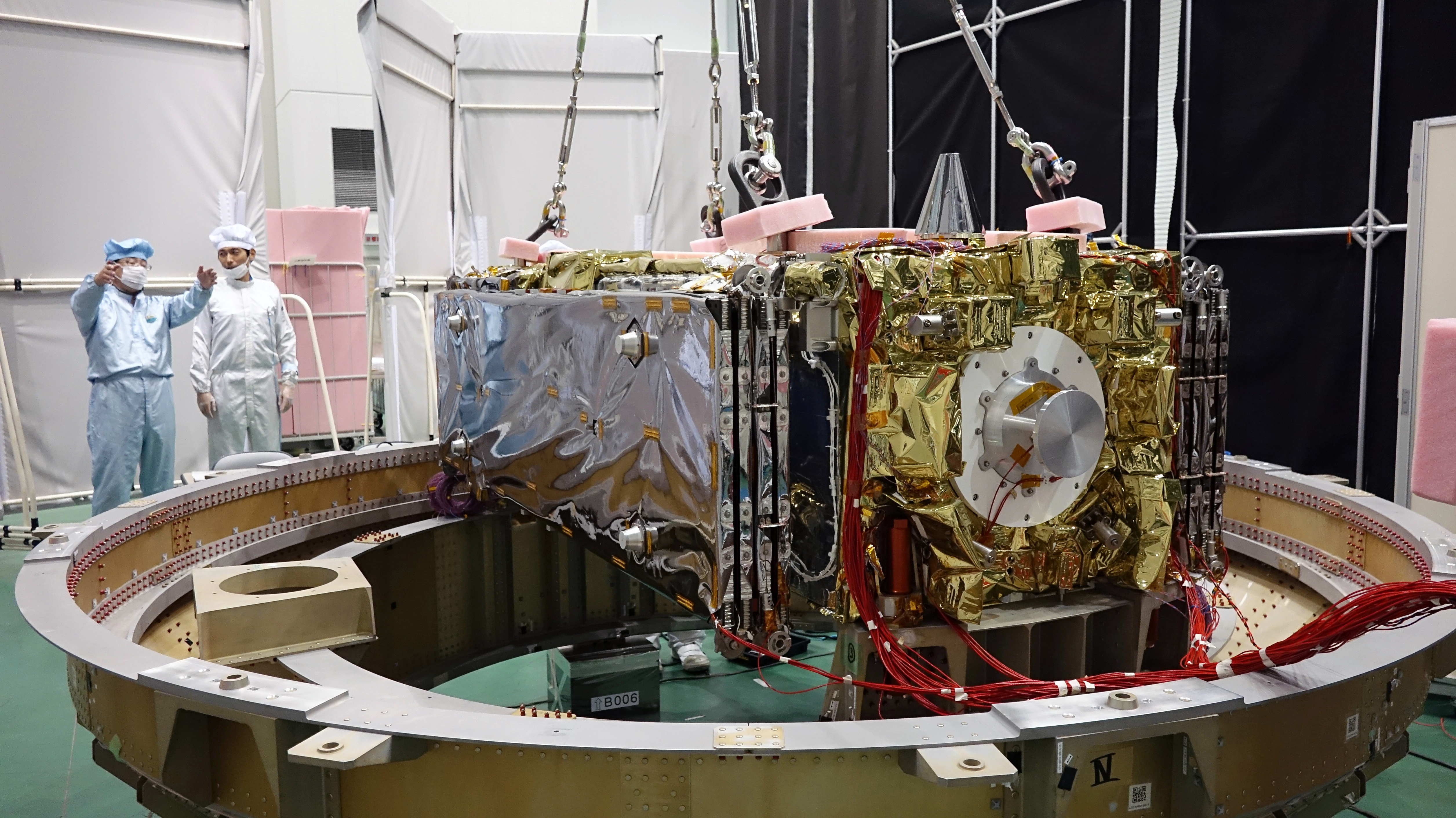
The SLATS satellite has a mass of ~400 Kilograms and measures 2.5 by 5.2 by 0.9 meters in size when its two four-panel solar arrays are deployed to deliver a minimum end of life power of 1,140 Watts given the satellite’s power requirement arising from the use of ion propulsion. One important design consideration was minimizing the area of the satellite’s ram-facing side to reduce drag, although no particular aerodynamic elements are used by the spacecraft and the forward facing side is occupied by the in-situ atomic oxygen sensors to face the inflow of particles. When packaged for launch, the satellite is 2525 x 1197 x 893 millimeters in size.
The satellite’s Electrical Power System accepts power from the solar arrays via a Solar Array Panel Shunt Unit which passes power to the Power Control Unit, tasked with controlling the state of charge of a Li-Ion battery and a primary voltage regulator passes power to the Power Distribution Unit that comprises five different power drive modules – 1) one dedicated drive regulating the magnetic torque rods based on inputs from the spacecraft controller, 2) a valve drive for the chemical propulsion system, 3) a thruster drive for the ion propulsion system, 4) a dedicated heater circuit to power survival and component heaters and 5) a secondary voltage regulator that distributes the satellite’s power bus to all subsystems.
The brain of the SLATS spacecraft is the Satellite Control Unit comprising two input/output modules to communicate with the various subsystems and payload, a dedicated input/output interface to the satellite’s communications system, an Attitude and Orbit Control module and the Central Processing Unit in charge of command execution and data handling.
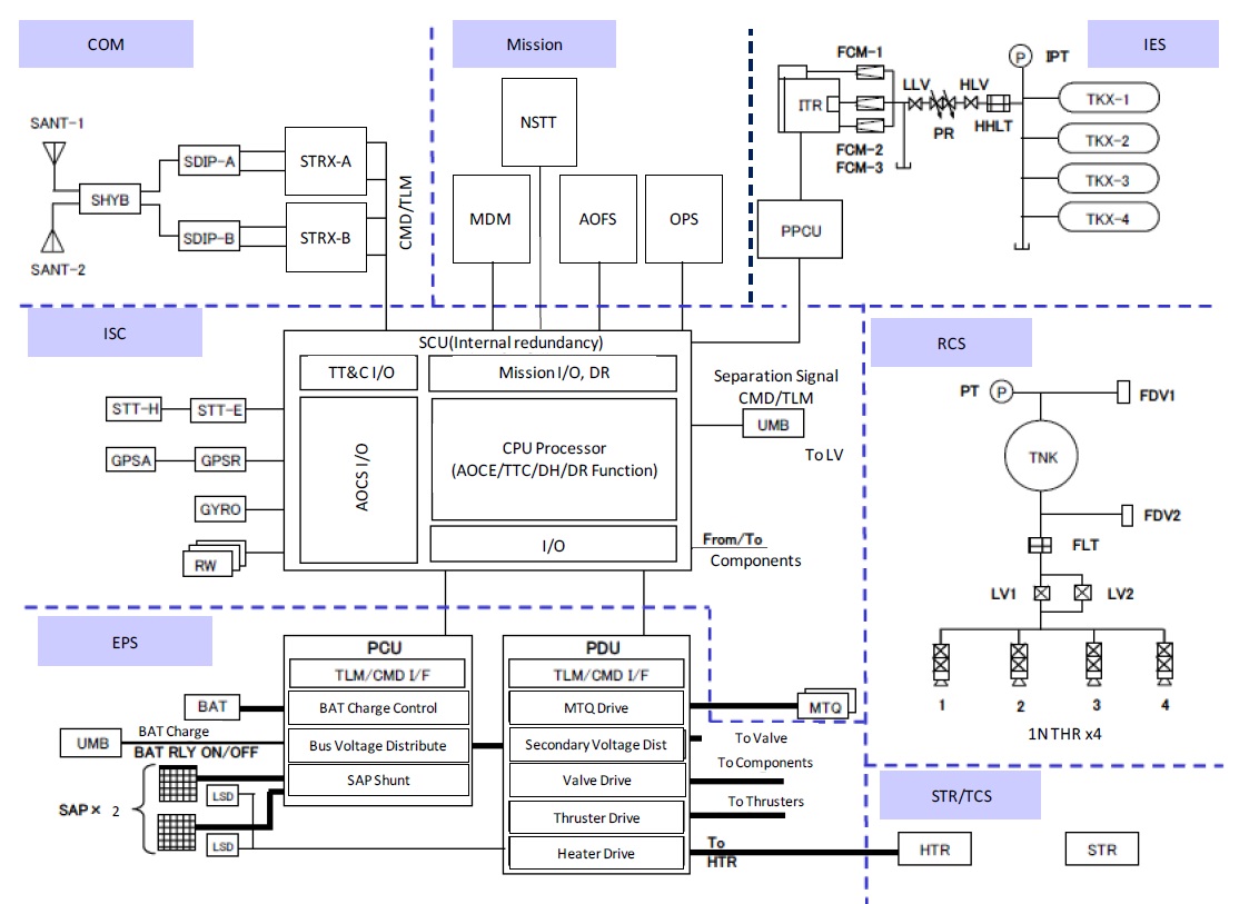

SLATS relies on a new type of Star Tracker known as the NSTT (Next Generation Star Tracker) as primary attitude determination sensor for fine control with a gyro package, magnetometer and sun sensors providing auxiliary information for initial attitude acquisition, safe mode control, torquer actuation and the measurement of deceleration caused by aerodynamic drag. Three flywheels and magnetic torquers provide attitude actuation with sufficient torques to keep the satellite stable even in high-drag environments.
The NSTT is a collaborative development between JAXA and NEC Toshiba Space Systems to realize a compact star tracker system with high accuracy to become an operational component for small satellite platforms.
NSTT weighs 6.2 Kilograms and requires under 20 Watts of power, comprising an optical head with a 16 by 16-degree field of view and an electronics unit that reads out the detector at a rate of four images per second, then processed to identify known stars from which the satellite’s precise three-axis orientation in space is calculated. It achieves an attitude determination accuracy of up to 4 arcsec and is capable of dealing with body rates of up to 3°/s for initial acquisition.
The satellite’s hybrid propulsion system employs a heritage chemical propulsion system with extensive flight history on a number of Japanese satellites and the Ion Engine System (IES) also draws heritage from previous programs but implements a number of new systems geared towards operation in the extremely low orbit regime.
The Chemical Propulsion System is a stripped-down version of a similar system employed on larger satellites in the two-ton range, the main difference being a reduction in redundancy by switching from two separate thruster banks to a single bank to comply with the mass and volume requirements for small satellite missions. It comprises a spherical tank holding 34 Kilograms of Hydrazine propellant and pressurization gas, operated in blowdown mode over the course of the mission (only requiring a one-time pressurization on the ground). The tank is connected to four 1-Newton monopropellant thrusters via a filter and a pair of redundant Latch Valves with each thruster comprising a set of redundant valves.
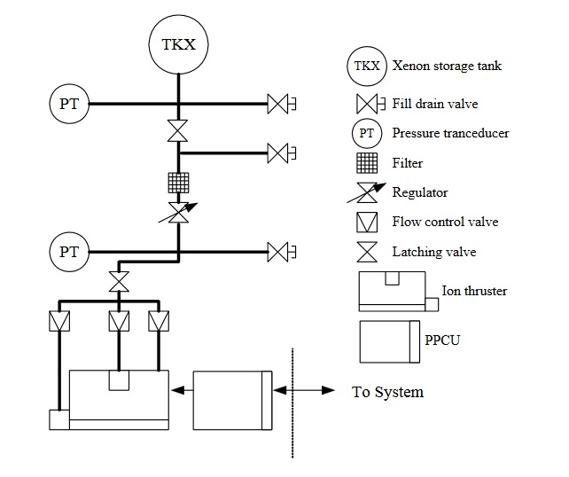
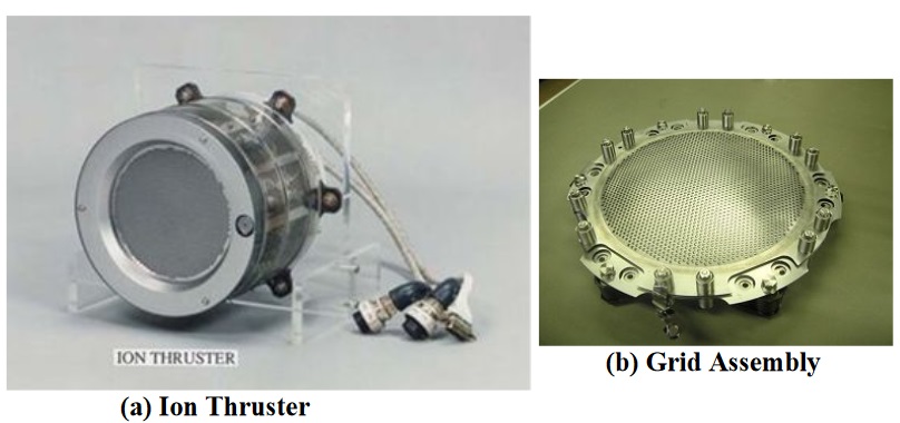
The Ion Engine System (IES) consists of three major building blocks – the Propellant Management Unit (PMU) featuring the tanks and propellant regulation equipment, the Power Processing Control Unit (PPCU) setting the various voltages needed by the engine, and the Ion Thruster (ITR) itself. The PMU is almost identical to that of the ETS-8 technology demonstration satellite while the PPCU and Thruster draw heritage from the propulsion system used on the Hayabusa probe but operate at higher performance and employ modifications for operation in very low orbits.
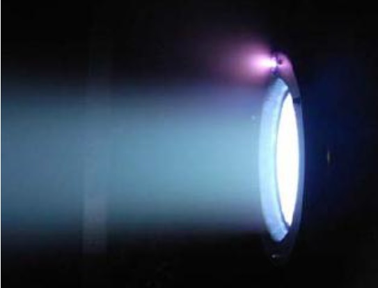
Ion thrusters generate thrust by accelerating heavy ions through the use of an electric field and ejecting these ions at extremely high velocity creating thrust force propelling the spacecraft forward. Although ion thrusters deliver a very low thrust, they are extremely efficient and consume only a very small amount of propellant. Through long operation of the thrusters, spacecraft can achieve changes in velocity of several Kilometers per second as demonstrated by Hayabusa 1 (over 2km/s), Deep Space 1 (4.3km/s), and Dawn (over 10km/s). While these missions used the thrusters to accelerate, SLATS will employ its IES to maintain a stable orbit, aiming to control IES to keep its velocity constant.
Ion thrusters use ions to create thrust in accordance with momentum conservation. The method of ion acceleration varies between the use of Coulomb and Lorentz force, but all designs take advantage of the charge/mass ratio of the ions to create very high velocities with very small potential differences which leads to a reduction of reaction mass that is required but also increases the amount of specific power compared to chemical propulsion.
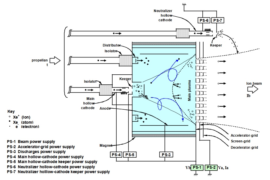
The thrusters operate by releasing small amounts of Xenon atoms that are then ionized through electron bombardment by using electron cyclotron resonance microwave discharge – a new design that eliminated solid electrodes and associated heaters that were used as part of previous systems. The same microwave generator is used to feed the ion generator and neutralizer which reduces overall mass of the assembly. The neutralizer emits electrons near the exiting ion beam to ensure that equal amounts of positive and negative charge are expelled, thus preventing the spacecraft from gaining an excessive electrical charge that could damage components.
The generated ions are extracted by a dedicated system consisting of electrically charged carbon-carbon grids with primary acceleration of the ions taking place between the first and second acceleration grids. The negative voltage of the accelerator prevents ions from the beam plasma outside the thrusters from streaming back which would decrease the generated thrust. The ejected ions push the spacecraft in the opposite direction according to Newton’s third law.
The Propellant Management Unit hosts three or four Xenon tanks (documentation differs on the number) holding a total of 12 Kilograms of Xenon propellant at a pressure of 70 bar. A high-pressure latching valve and pressure regulator condition the flow of Xenon to the thruster where a low-pressure regulator and mass flow control devices (fixed orifice devices) set the Xenon flow rate to 10.5 cm³/s including a flow of 2.0 cm³/s into the neutralizer.
The PPCU and ITS, a development of JAXA and Mitsubishi Electric, is a new 20-Millinewton class ion engine system specifically employed for drag compensation, capable of operating at a thrust of 10 to 28 mN and achieving a specific impulse of 2000 seconds with a lifetime expectation of 16,000 hours (satisfying the two-year mission life requirement for SLATS and its operational successors). The nominal thruster setpoint for IES will be 17mN at a total power requirement of 580 Watts.
The PPCU accepts the 28-Volt (24-32V) power bus from the PDU and hosts a total of seven power supplies delivering the various voltages for operation of the ion thruster which range from 15 to 1,100 V at currents of 0.01 to 5.5 A and a power draw from 1.5 to 660 Watts for the different engine components. All in all, the complete IES system weighs 43 Kilograms.

Operation of the Ion Engine System is completed in closed-loop control on board the satellite when SLATS is operated in its orbit-keeping mode. Using inputs from redundant GPS receivers, the Spacecraft Control Unit will constantly calculate its orbit and compare it to the required altitude corridor for the current mission phase and, based on these parameters, send power-on and power-off commands to the thruster.
Per its demonstration mission plan, SLATS will be released into an initial orbit of 450 x 643 Kilometers, 98.3° thanks to a newly developed technology on the H-IIA F37 launch vehicle that demonstrates the vehicle’s multi-orbit mission capability. Flying at a safe altitude where aerodynamic drag is negligible for the short term, SLATS will undergo deployment and checkout including GPS orbit determination validation and initial IES testing.
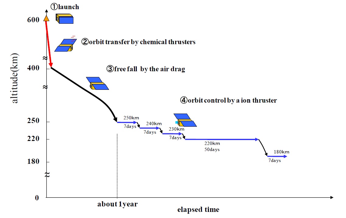
Through the use of its chemical propulsion system, SLATS will maneuver into an orbit around 400 Kilometers in altitude while simultaneously conducting out of plane maneuvers to set up the proper inclination and ascending node. From 400 Kilometers, drag will take over and lower the orbit to 268 Kilometers in around one year’s time where the Super Low Orbit testing phase will begin. Initial testing at this altitude will provide several weeks of margin in case the satellite temporarily loses its ability to maintain the orbit through either propulsion system.
Then, the orbit will be lowered in ten-Kilometer increments every week until arriving at 220 Kilometers where SLATS is expected to maintain altitude for two months which will conclude the primary mission. For its extended mission operations, SLATS will be allowed to decay to 180 Kilometers where it will have to use its Ion Engine System at full duty cycle and perform supplementary firings of its chemical thrusters to maintain its altitude in an extreme drag environment.
While making its descent from 268 to 180 Kilometers, SLATS will deliver valuable information on the air density at these LEO altitudes which are not measured regularly since satellites cross these altitudes quickly when approaching orbital decay.
Traversing a fairly unique orbital regime, SLATS will make use of the opportunity by studying the density of atomic oxygen and its effect on the satellite while also demonstrating the benefits of orbiting closer to Earth by employing an inexpensive Optical Sensor.
Atomic oxygen can not exist naturally on Earth’s surface for very long, but in Low Earth Orbit where no protection exists for incoming ultraviolet radiation, atomic oxygen represents an abundant species with a total of 96% of all oxygen occurring in an atomic form. Due to its atomic structure, the species is extremely reactive since the single free electron of the oxygen radicals tend to quickly bond with nearby molecules. Oxidation of satellite components in LEO is therefore a common problem and has to be considered by spacecraft designers.
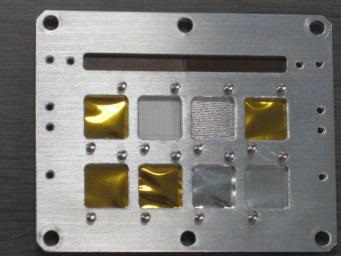
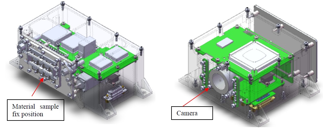
As atmospheric density increases, so does the concentration of atomic oxygen, meaning any future Super Low Earth Orbit missions will have to deal with a much harsher environment than their counterparts at 400 Kilometers and up. To explore the effects this environment has on some commonly used materials, SLATS hosts a Material Degradation Monitor (MDM) on the +Z panel of the satellite, facilitating a dozen different samples and a camera to document visible degradation of the sample materials.
The samples flown by MDM are broken down into three categories: 1) Multilayer Insulation typically used outside satellites (a polyimide-aluminum based MLI, polysiloxane-aluminum MLI, Atomic Oxygen Protective Coating, beta cloth), 2) cable insulator material (three types of Expanded PTFE cable, ETFE cable), and 3) solar array coatings (ITO/5mm FEP/Silver, 1mm FEP Film/Silver, 5mm FEP Film/Silver). A 380,000-pixel CCD camera is tasked with observing the samples at regular intervals during the mission.

The Atomic Oxygen Fluence Sensor is installed on the ram side of the SLATS spacecraft and primarily consists of a Thermoelectric Quartz Crystal Microbalance (TQCM) sensor which measures the minute loss of mass on the crystal oscillator electrode surface as a result of erosion of its polyimide coating by atomic oxygen collisions. The measured variable is the frequency of the oscillator that changes with the mass of the oscillating material. A polyimide-free TQCM is installed next to the sensor to assess contamination effects and a shutter is employed for both to control the time the electrodes are exposed to the oxygen influx.
The Optical Sensor for Earth Observation will be used to demonstrate the increase in spatial resolution coming with decreasing altitude by acquiring imagery from the altitude SLATS starts out at and then when under 250 Kilometers from the surface.
