
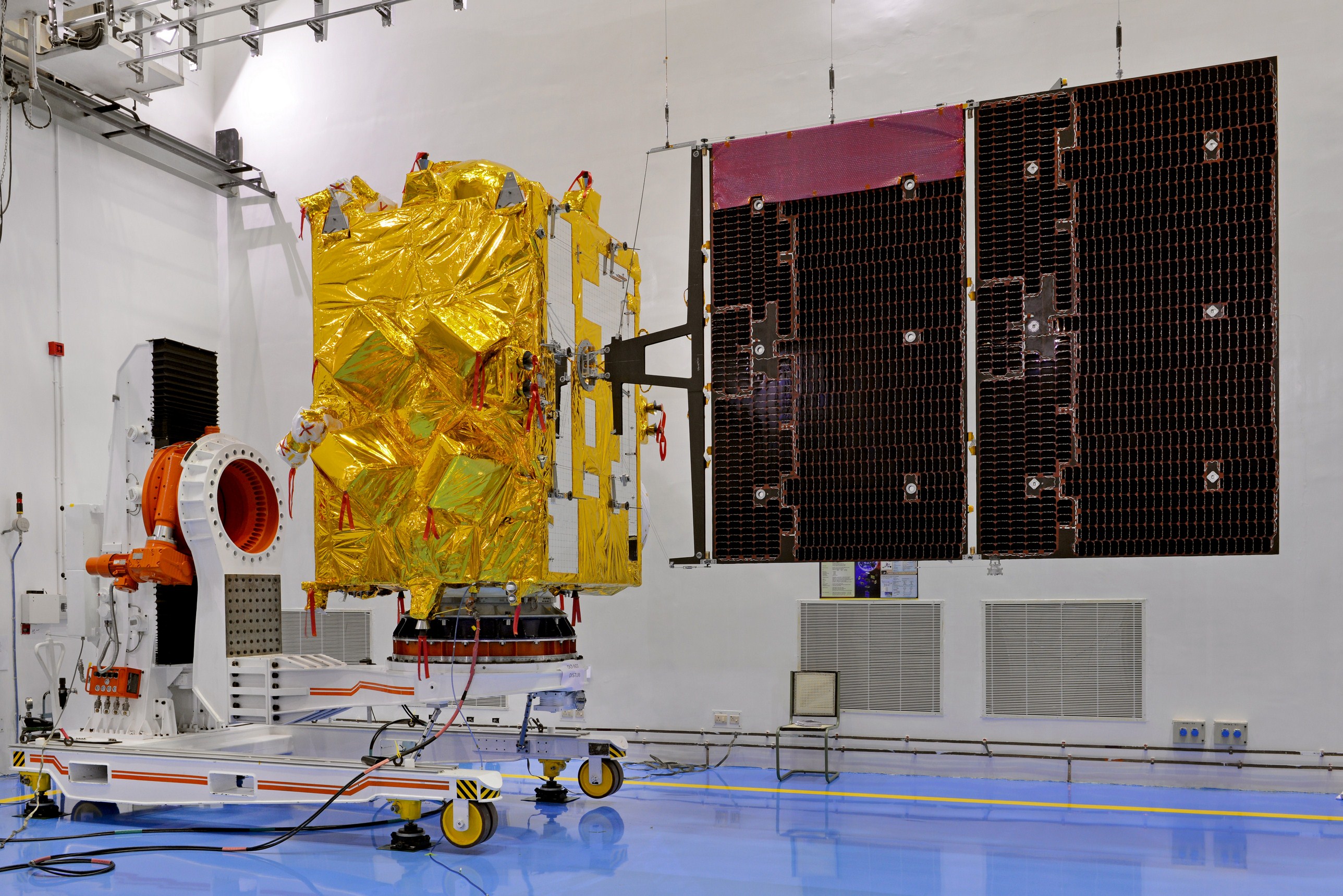
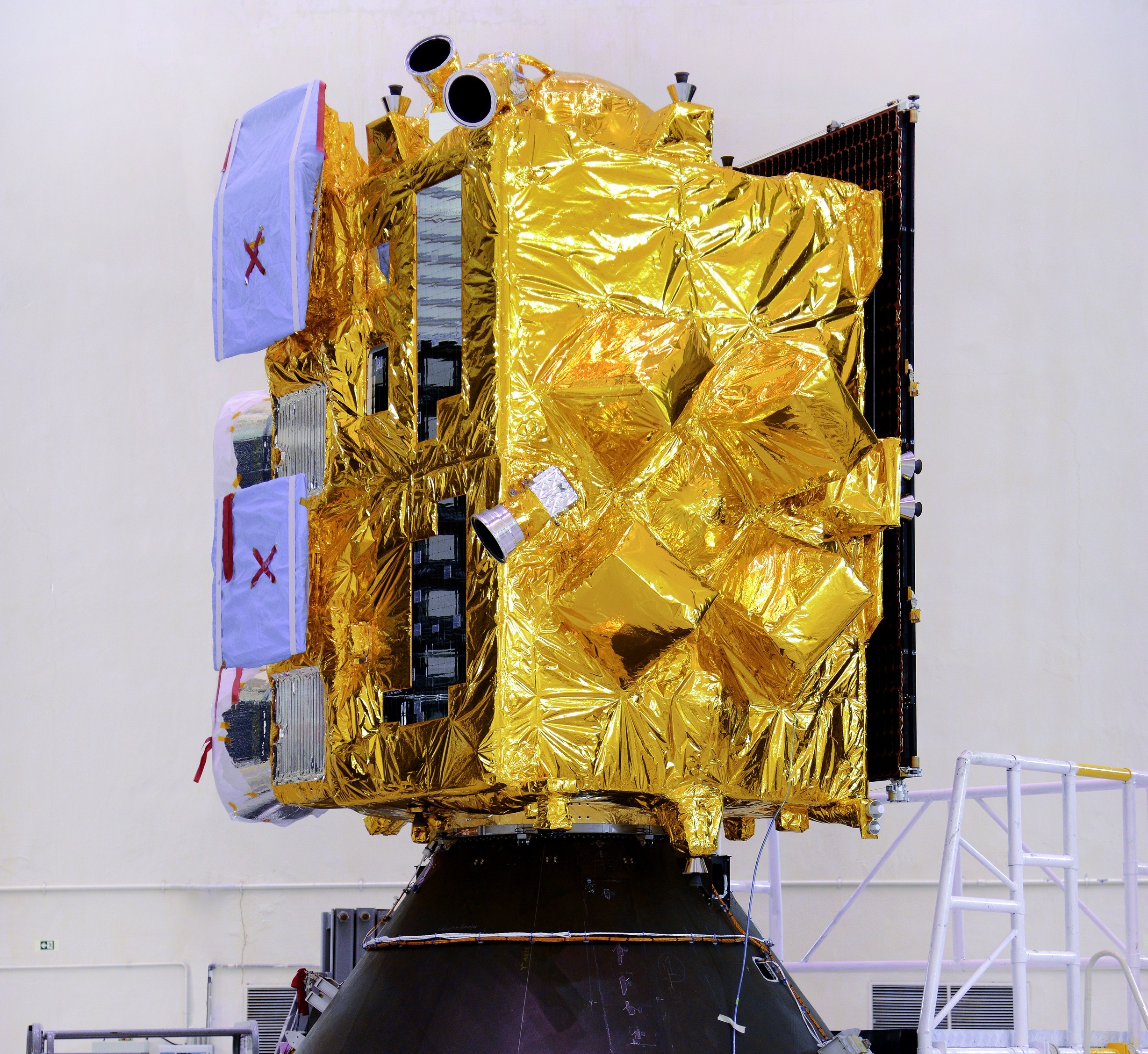
INSAT-3DR Satellite
INSAT-3DR is an Indian weather satellite flying under the full name Indian National Satellite 3D Repeat. The satellite was manufactured by the Indian Space Research Organization and is operated by INSAT to collect data relevant for operational weather nowcasting and forecasting using an imaging and sounding payload deployed to Geostationary Orbit.
The INSAT-3DR mission is a follow-on to INSAT-3D which launched in July 2013 aboard an Ariane 5 launch vehicle to operate from a position of 82° East in Geostationary Orbit. INSAT-3DR is almost a carbon copy of the 3D satellite, but will use India’s indigenous GSLV Mk.II rocket as its launch vehicle.
The INSAT-3D program was initiated as a next-generation mission for the collection of enhanced data for meteorological observations and monitoring of land and ocean surfaces in support of weather forecasting and disaster warning.
INSAT data is shared with the National Oceanic and Atmospheric Administration in the United States in exchange for U.S. Earth Observation data & information. Also part of the Indo-US collaboration is the exchange of data processing techniques and the deployment of a data link between the data processing architectures of the Indian and American programs.
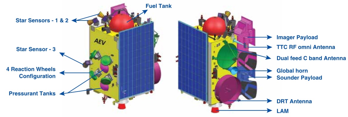
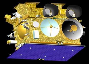
INSAT-3DR is based on ISRO’s I-2K satellite bus for satellites in the 2,000 Kilogram mass range, suitable for different applications including communications and meteorology. The satellite has a dry mass of 956 Kilograms and a bus size of 2.4 by 1.6 by 1.5 meters. Fueled for launch, the spacecraft weighs 2,211 Kilograms including propellants for its climb to Geostationary Orbit and stationkeeping once arriving in its operational slot. The spacecraft structure makes use of lightweight honeycomb panels with aluminum/CFRP face-sheets connected to a central cylinder that acts as the load-carrying structure, running the entire length of the vehicle and facilitating the propellant tanks.
INSAT-3DR hosts a deployable solar panel covered with Advanced Triple Junction solar cells that generate 1,700 Watts of electrical power fed to a 90 Amp-hour Li-Ion chemical battery. A micro-stepping device is employed as a Solar Array Drive Assembly, pointing the solar array toward the sun. The satellite’s central power bus is regulated by a central EPS unit.
The Propulsion System features two spherical propellant tanks facilitated within the central cylinder of the spacecraft. INSAT-3DR uses Unsymmetrical Dimethylhydrazine as fuel and Mixed Oxides of Nitrogen [MON-3: Nitrogen Tetroxide with 3% Nitric Oxide] as oxidizer that is fed to the engines via propellant lines facilitating pressure regulators. Tank pressurization is accomplished with high-pressure Helium stored at a pressure of 23.5Mpa that is regulated down to under 2MPa for tank pressurization.
The Main Propulsion System is centered around the Liquid Apogee Motor providing 440 Newtons of thrust, operating at a mixture ratio (O/F) of 1.65. It has a nozzle ratio of 160 providing a specific impulse of 3,041N*sec/kg. The engine’s injector is a co-axial swirl element made of titanium while the thrust chamber is constructed of Columbium alloy that is radiatively cooled. Electron welding technique is used to mate the injector to the combustion chamber.
LAM is a robust engine that can tolerate injection pressures of 0.9 to 2.0 MPa, propellant temperatures of 0 to 65°C, mixture ratios of 1.2 to 2.0 and bus voltages of 28 to 42 Volts. The engine is certified for long firings of up to 3,000 seconds and a cumulative firing time of >23,542 seconds.
The INSAT Attitude Determination System makes use of Star Trackers and Earth Sensors as the primary source of pointing information to achieve a very stable Earth-pointed orientation due to stringent payload pointing requirements. The payloads dictate a stability of two pixels over the long-term in support of Mirror Motion and Image Motion Compensation. Secondary attitude sensors include Digital Sun Sensors, Coarse Sun Sensors in use during spacecraft safe mode, Solar Panel Sun Sensors and an Inertial Measurement Unit.
Attitude Actuation is provided by two momentum wheels and a reaction wheel assisted by the 22-Newton thrusters when needed for wheel unloading, stationkeeping and attitude control including a bi-annual yaw rotation to properly point the satellite’s thermal radiators to cold space.
The INSAT-3DR satellite employs a Bus Management Unit as the central computing unit of the spacecraft. It features a MAR 31750-type microprocessor and 1553 interfaces for the exchange of data with all satellite subsystems. The onboard computer is in charge of accepting and executing commands from Earth, handling telemetry from all subsystems, processing and storing instrument data and controlling all payload functions.
The communications system makes use of the C-Band frequency band to independently downlink data from the two satellite instruments, the Search and Rescue Payload and the Data Relay Transponder. A 30MHz band from 4770 to 4800 MHz is required for the downlink of the imager and sounder data using a redundant chain of redundant transmitters. INSAT-3DR uses an omni-directional antenna for the downlink of payload data.
The Data Relay Transponder accepts UHF signals (406MHz) from various Data Collection Platforms on Earth and downlinks the collected data in C-Band at 4500 to 4510 MHz.
INSAT Imager
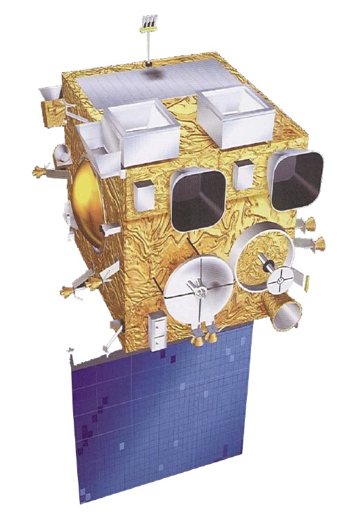
The INSAT-3DR payload is comprised of a Six-Band Imager, a 19-Band Sounder, the Data Relay Transponder and Satellite Aided Search And Rescue communications package. The two new-generation meteorological instruments are designed to deliver a comprehensive data set for Earth surface, oceanic and atmospheric observations.
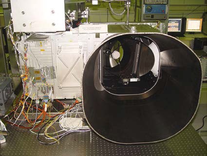
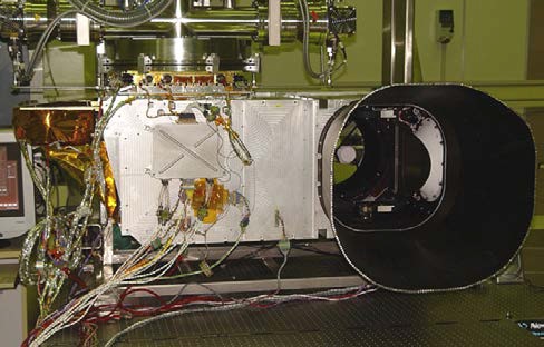
The imager, similar to that flown on the original INSAT-3D mission, uses heritage from the VHRR/2 (Very High Resolution Radiometer) that flew on previous missions, but expands its capabilities by doubling the number of observed bands and improving the spatial resolution of the instrument. The 130-Kilogram instrument is comprised of a moving scanning mirror and a reflective telescope feeding a cooled focal plane assembly covering the infrared and visible bands.
Monitoring the entire disk of the planet at a time resolution better than 30 minutes, the imager delivers data at a ground resolution between one and four Kilometers. Its data will permit the calculation of sea surface temperature, atmospheric water content, cloud motion and height, plus other general weather monitoring tasks for now- and forecasting purposes.
Light enters the instrument through a 31-centimeter entrance featuring a large sunshade to eliminate stray light from the sun. The elliptical Silicon-Carbide Scan Mirror is driven by a two-axis gimbaled servo system, mounted 45° to the optical axis. Two independent servo loops are used to drive the mirror about two axes to sweep across the planet and assemble global imagery through successive scans of the entire disk.
Motion on the two axis are driven by limited angle torquers on the fast-scan axis and shafts on the slow axis. The fast-scan axis accomplishes the east-to-west sweep of the instrument while the slow scan axis steps the mirror for north-to-south imaging with each successive east-west pass. The fast scan motion occurs between +/-4.5 degrees about the fast scan axis with one sweep taking only 0.9 seconds. The 9-degree scanning motion can be positioned within an overall field of regard of 12 degrees. After an E-W scan, the mirror steps south by a ground distance of 8 Kilometers for the next scan which then goes from West to East.

The Scanning Mirror feeds a Cassegrain Telescope consisting of two-mirrors placed on the optical axis of the telescope – a concave M1 primary mirror 310 millimeters in diameter and a 50mm on-axis convex M2 mirror that focuses the light onto the Focal Plane Assembly via aft optics that are in charge of folding the flight onto the different detector elements via folding mirrors, collimators and dichroic optical elements that separate the different wavelength bands.
The instrument hosts six detectors requiring five dichroic elements. The first separates the visible light from the incoming beam and directs it to a fold mirror to pass into the uncooled VIS detector. The separated infrared beam is collimated and passes through four dichroic elements to be separated into the short-wave, mid-wave and thermal wavelengths that are directed through bandpass filters to the corresponding detectors which reside within a cooler assembly.
The imager employs a three-stage passive cooler to maintain the detectors at a temperature of 95 Kelvin by radiating excess heat into space, thus reducing dark currents on the IR detectors. The redundant radiator assembly on the outside of the satellite is pointed at cold space throughout the year by making two annual yaw rotations of the entire satellite to avoid solar irradiation of the radiators, thus maintaining a carefully planned thermal budget.
The visible detector element consists of an array of silicon photodiodes comprised of 16 elements, eight for primary use and eight redundant arrays sensitive in the 550 to 750-nanometer wavelength range. Each of the elements has a geometric field of view of 28 microradians (square) corresponding to a spatial resolution of 1 by 1 Kilometer per pixel at nadir.
Each VIS channel employs a Read-Out Integrated Circuit with capacitive trans-impedance amplifiers coupled to an output buffer and multiplexer to reduce readout noise and simplify the processing chain.
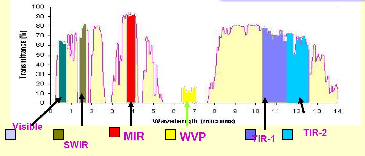
The Short-Wave Infrared Channel covers a wavelength range of 1.55 to 1.70 µm using a similar detector arrangement to VIS, but employing Indium Gallium Arsenide detector elements coupled to resistive trans impedance amplifiers for pre-amplification. The detector is maintained at +15°C and also achieves a 1 x 1 km resolution.
The Mid-Wave and two Thermal Infrared channels each contain four detector elements, two as primary and two for redundancy, while the Water Vapor Channel hosts only two elements. The MIR channel utilizes Indium Antimonide photodiodes for detection at the 3.80 – 4.00 µm wavelength with pre-amplifiers integrated with the detector elements due to the high-impedance of the InSb elements.

All three remaining IR channels make use of Mercury Cadmium Telluride elements – the Water Vapor Channel covers the infrared range of 6.50 – 7.10 µm while the two thermal channels are sensitive for wavelengths of 10.3 – 11.3 µm and 11.5 – 12.5 µm. The MIR/TIR detector elements have a field of view of 112 microradians corresponding to a 4 x 4 km ground resolution; the WV channel covers squares with an 8-Kilometer side length.
The instrument operates at a sampling rate of 21840 samples per second for the VIS/SWIR channels and 5460 samples/s for the infrared channels with a scan rate of 20°/s which creates over sampling by all of the channels in the E-W direction. This creates a frame assembly time of 25 minutes and a data rate of 4Mbit/s.
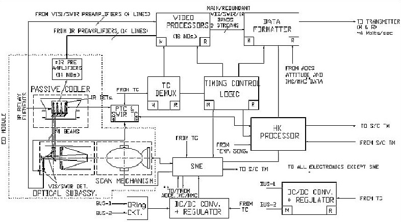
The support electronics of the imager include telemetry and command demultiplexers, a video processor and data formatter in charge of processing instrument data, a housekeeping telemetry processor, and a pair of DC/DC converters.
Another consideration in the design of the imager is its coupling with the sounder on the same spacecraft which will create some instrument-to-instrument interference in the form of vibration and spacecraft attitude instability. The effect of this disturbance on the imager’s scanning mirror is calculated in real time as part of the satellite’s attitude logic and a correction signal is sent of the Imager Scan Mirror Drive Mechanism to compensate by slightly modifying the scan mirror pointing for the expected attitude effects. This real-time correction reduces the amount of processing to be done on the ground to ensure proper repeatability of geo locations on the pixel detectors.
INSAT Sounder
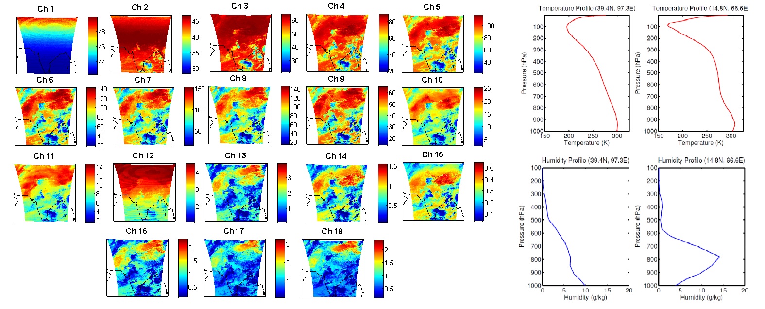
The Sounder is tasked with the measurement of vertical temperature and humidity profiles in Earth’s atmosphere to obtain a three-dimensional representation of the atmosphere at high temporal resolution. The instrument achieves a ground resolution of 10 Kilometers and delivers a full frame every 160 minutes. Its data is put to use when calculating atmospheric instability, water content, carbon dioxide, ozone, oxides of Nitrogen, and visible phenomena.
In its basic design, the sounder is very similar to the imager instrument, comprised of an electro-optical imaging system with moving scan mirror supported by a series of electronics modules. The instrument consists of a scan assembly, telescope, focal plane assembly and electronics.
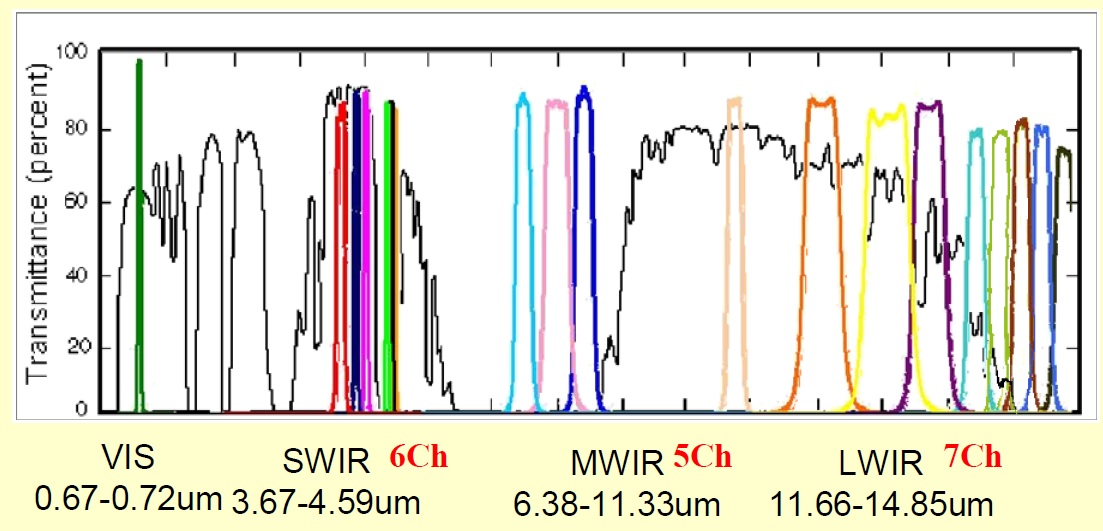
The 145-Kilogram instrument covers 18 infrared and one visible channel at a ground resolution of ten Kilometers, collecting an image frame every 100 milliseconds. Sensitivity of the instrument extends across a broad area of the infrared spectrum from 3.7 to 14.7 µm plus the single VIS channel at 695 nanometers.
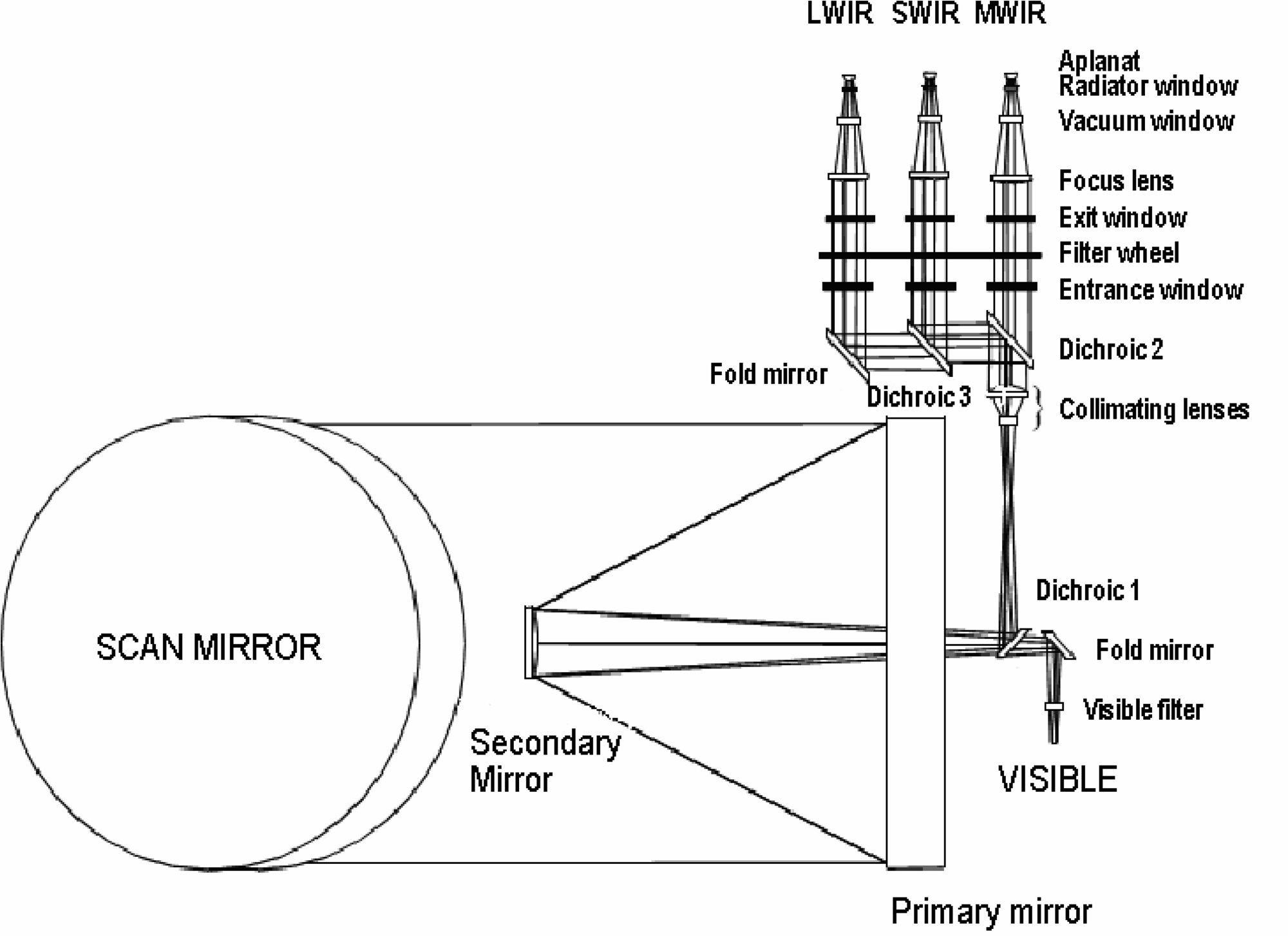
The Sounder also makes use of a bi-directional Scanning Mirror that selects the viewable field of view by employing a fast-scan mechanism for the East-West direction and a stepping device to move south by 1120 microradians after each line is scanned. Light from the scanning mirror is fed to a Cassegrain Telescope with 310mm primary and 50mm secondary mirror that focuses the beam onto the focal plane assembly which is comprised of two separate units.
A dichroic element separates the visible wavelengths that are directed to a folding mirror and onto the VIS focal plane that is separate from the infrared system. The infrared detector system hosts a collimator lens and two dichroic systems to separate short, mid- and long-wave infrared radiation directed to a cold filter wheel that selects the infrared band within each of the three split beams sent to the passively-cooled detector assembly.
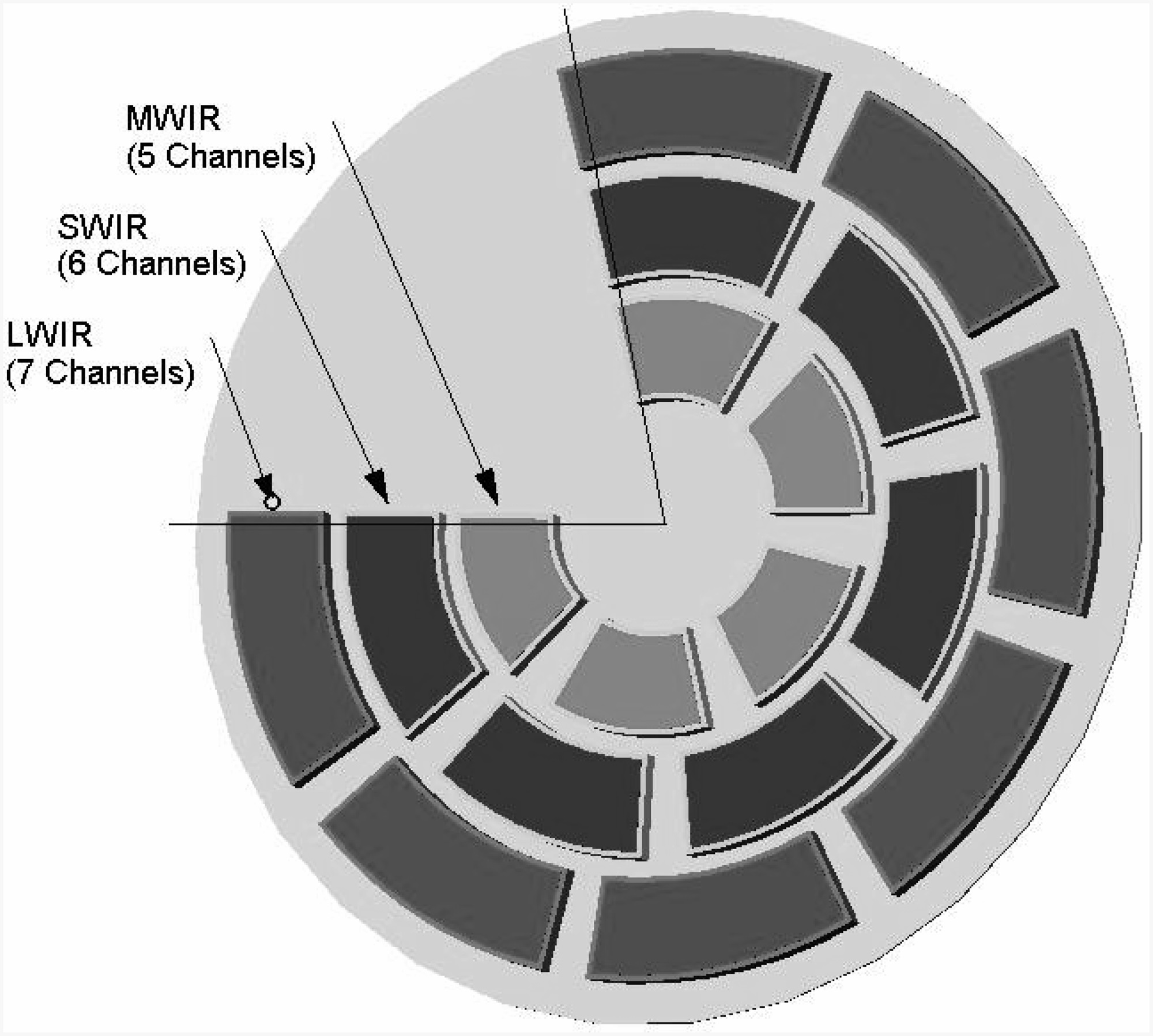
The filter wheel has 18 windows in three concentric rings to cover 7 long-wave IR channels, 5 mid-wave and 6 short-wave channels. The length and gap of each filter element has been optimized for performance considering the size and rotation speed of the wheel. Almost 20% of the wheel is blank to block the optical path when the scan mirror completes its scene steps. While sounding, the scanning mirror is held stationary and a period for stabilization is included in the sounding algorithm.
The filters on the wheel define the spectral range for each of the 18 channels and therefore stringent thermal requirements exist for the wheel. It is cooled to 213K (+/-1K) using a cooling system separate to that of the detector assembly.
The motion of the scan mirror is tightly coupled to the operation of the filter wheel to set the sounding operation in terms of observation position and wavelength. At each mirror position, the wheel rotates and sequentially places all 18 spectral filters into the optical paths with corresponding detector read-out cycles.
At the operational rotation of 600RPM, it takes only 80ms for all filters to be rotated across the detectors followed by 20ms for Scanning Mirror motion and stabilization, creating an integration length of 100 milliseconds. Up to four integrations can be taken for each mirror position for a length of 400 ms. (As evident in the instrument design, the visible channel is sampled independent of filter wheel position)
The sounder measures radiance over an instantaneous field of view of 10 km in the East-West direction and 40 km in the North-South direction. Typically, the instrument completes scans of 640 x 640-Kilometer blocks that can be located anywhere in the 24 by 19-degree field of regard. The generation of a complete 6400 x 6400-Kilometer frame takes two hours and 40 minutes.
The Sounder uses four separate detector assemblies, each comprised of four elements in the North-South direction – each element corresponds to 10 x 10 km on the ground.
The visible detector element consists of an array of silicon photodiodes sensitive in the 670 to 720-nanometer wavelength range. An array of Indium Antimonide detectors with integrated pre-amplifiers is used for the detection of short-wave infrared while the mid and long-wave channels employ Mercury Cadmium Telluride elements. The IR detectors are kept at a temperature of 95K with very high stability to reduce dark currents.
Per the normal operating procedure, the scan mirror points to a deflection of 9 degrees after every 1,216 filter wheel rotations (~2 minutes) to capture a calibration frame cold space. Also, roughly every 30 minutes, a calibration using an internal blackbody source of known properties is performed to establish a high-temperature baseline. Some of the space views are accompanied by the injection of an electrical calibration signal of sixteen steps to check for the stability of the amplifier circuits.
The Sounder can operate in different modes, typically assembling large frames when in its routine operations mode, but observations can be quickly re-targeted to observe dynamic phenomena within the atmosphere.