
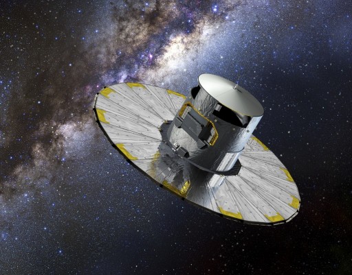
Gaia Spacecraft Overview
The Gaia Spacecraft consists of a Payload Module, a Mechanical Service Module and an Electrical Service Module amounting to a total spacecraft mass of 2,030 Kilograms. In its deployed configuration, Gaia is approximately 3.5 meters long and 10 meters in diameter.
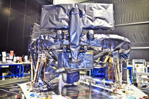
Service Module
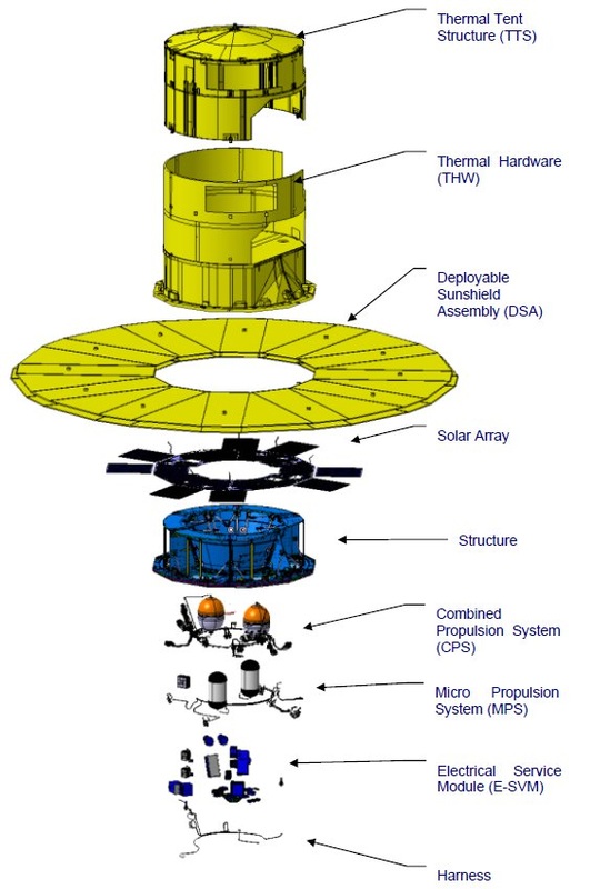
The Mechanical Service Module includes all mechanical, structural and thermal elements that support the instrument payload and spacecraft electronics.
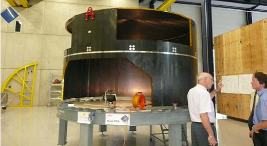
It also includes the Chemical & Micro Propulsion Systems, the Deployable Sunshield with Solar Arrays, the Payload Thermal Tent and harness. The module consists of a central tube that is about 1.17 meters long and hosts six radial panels to create a hexagonal spacecraft shape.
The bottom floor is a dodecagonal-shaped panel to comply with the 12 frames of the Deployable Sunshield Assembly (DSA). The main structure consists of carbon-fiber reinforced plastic facesheets.
The outer panels of the Service Module hosts the Video Processing Units and Payload Data Handling Electronics.
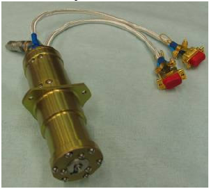
Micro Propulsion System
Gaia uses a Micro Propulsion System for fine attitude pointing and spin rate management. The MPS itself consists of the Micro Propulsion Feed Module, Micro Thruster Assemblies and Micro Propulsion Electronics.
A total of 12 Cold Gas Thrusters are installed on the spacecraft being grouped in three clusters each featuring four cold gas thrusters. The thruster system uses high-pressure Nitrogen propellant to provide very small impulses with a thrust range of 1 Micronewtons to 500 Micronewtons (0.102 to 51 Milligram-Force). The System uses two ARDE Nitrogen Tanks, each containing 28.5 Kilograms of Nitrogen, stored at a pressure of 310 bar.
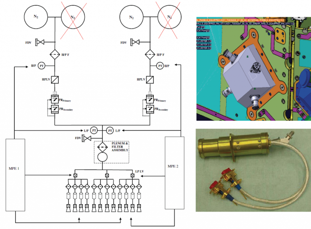
The two N2 tanks are filled via a single Fill & Drain Valve and supply gas to the propulsion system via a High Pressure Transducer and a High Pressure Latch Valve that pass the gas to two Pressure Regulators (a primary and a secondary) that reduce the gas pressure.
Two Low Pressure Transducers then direct the gas to three Low Pressure Latching Valves that are installed in the Micro Thruster Assemblies – each feeding four thrusters. The MPS pipes are 1/8” Titanium Alloy lines. The thrusters contain valve systems that are commanded via the Micro Propulsion Electronics Assembly. Each electronics unit controls one string of high/low pressure latching valves and six thrusters to provide some fault tolerance.
Each of the thrusters is operated at a low inlet pressure of 1 to 2 bar with a tolerance of up to 4 bar. The Micro Thrusters operate at an N2 mass flow of 0.002 to 1 Milligram per second. The thrusters tolerate more than 500 million on/off cycles and have a lifetime of 20,000 hours at an operational temperature of –20 to +50°C.
Micro Propulsion System Architecture
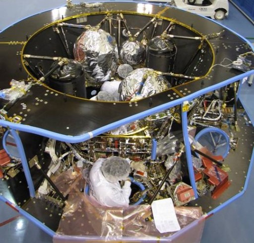
Chemical Propulsion System
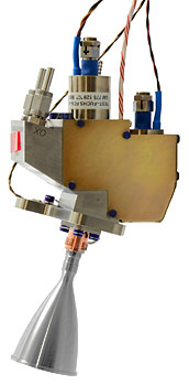
In addition to the Micro Propulsion System, Gaia is equipped with a Chemical Propulsion System using a Bipropellant System. Two Tanks with Herschel/Planck heritage are filled with a total of ~400kg of propellant featuring a blowdown ratio of 4:3. The tanks are mounted on the central tube via support struts. Gaia’s Chemical Propulsion System uses Monomethylhydrazine as fuel and Nitrogen Tetroxide as Oxidizer. The tanks feed two banks of six 10-Newton (1.02kg) thrusters that are mounted for burns in the +/-X axis directions with torquing function along the remaining axes for three-axis control. Four thrusters of each bank are installed oriented to the –X direction while two are oriented to the +X direction at an angle of 45 degrees to the Service Module structure.
The 10-Newton thrusters are manufactured by Astrium consisting of a platinum alloy combustion chamber and nozzle that tolerates the operational temperature of 1,500°C. The thruster can be operated in a thrust range of 6 to 12.5 Newtons with a nominal thrust of 10-Newtons which generates a specific impulse of 291 seconds. It operates at an inlet pressure of 10 to 23 bar and a chamber pressure of 9 bar. The engine operates at a nominal propellant flow rate of 3.5 grams per second and a mixture ratio of 1.65 with a possible range of 1.2 to 2.1. The thruster has a throat diameter of 2.85mm while the engine nozzle is 35mm in diameter and has an expansion ratio of 150. The 10N thruster has a qualified accumulated burn life of 70 Hours with up to one million duty cycles.
The Chemical Propulsion System is used for orbit insertion maneuvers, stationkeeping and large attitude corrections.
Guidance, Navigation & Control
Gaia is required to provide ultra-precise pointing and a low vibration environment which means that no moving parts can be present on the vehicle including the Gyroscopes. Therefore, Gaia’s Attitude and Orbit Control sub-System (AOCS) uses gyroscopes without rotating wheels. The vehicle uses three Fibre-Optics Gyroscopes (FOGs) that use the interference of light to detect mechanical rotation. Each unit contains four closed-loop gyroscope channels to provide built-in redundancy.
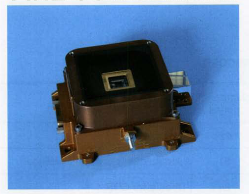
In addition to Gyroscopes, vehicle orientation and position is determined by the use of star trackers that provide data to the Command & Data Management Unit of the spacecraft. Also, Gaia uses three Fine Sun Sensors to provide attitude data. It measures the Sun’s presence as well as solar direction via an analog sensor based on a quadrant silicon photodiode located just behind a square aperture with a field of view of 128 deg x 128 deg. The three sensors use triple majority voting as part of the fault tolerant design of Gaia.
Fiber Optic Gyro
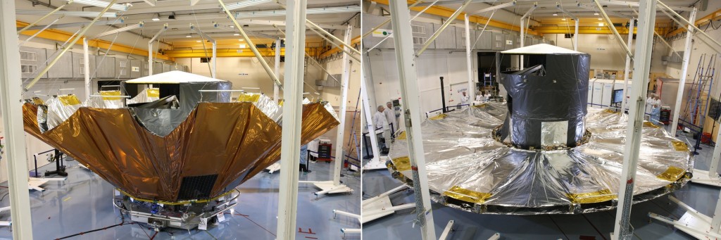
Deployable Sunshield Assembly
Gaia is equipped with a large Deployable Sunshield Assembly, DSA, that is folded up during launch and is deployed early in the flight. It is required to shade the payload unit and protect it from direct sunlight that could compromise instrument accuracy. Keeping the instrument at a constant temperature prevents expansion and contraction during temperature variations which would alter the instrument geometry ever so slightly with a large effect on data quality. The DSA is 10 meters in diameter.
The DSA is an umbrella-type structure that consists of Multilayer Insulation as the primary shield material and six rigid deployment booms as well as six secondary stiffeners. These booms have a single articulation on the base of the Service Module for easy deployment in the radial direction by a spring system. Spacing cables link the booms to the others to ensure a synchronized deployment sequence. The booms and strings are located on the cold side of the cover to limit thermo-elastic flexing.
Power & Data System
Attached to the DSA are six rectangular solar panels that are constantly facing the sun once the shield is deployed. The triple-junction Gallium-Arsenide solar arrays have a total surface area of 12.8m² and provide 1,910 Watts of end-of-life power to the spacecraft. A single low-weight 72 Amp-hour Li-Ion Battery is used during launch and before DSA deployment and when vehicle power demand exceeds the power provided by the solar arrays.
Power control and distribution is accomplished via a dedicated Power Control and Distribution Unit. The PCDU performs power management by generating a 28-Volt primary power bus that supplies power to each of the spacecraft units. It also controls the battery state of charge and generates pyrotechnic commands as well as heater actuation as commanded by the Command & Data Management Unit.
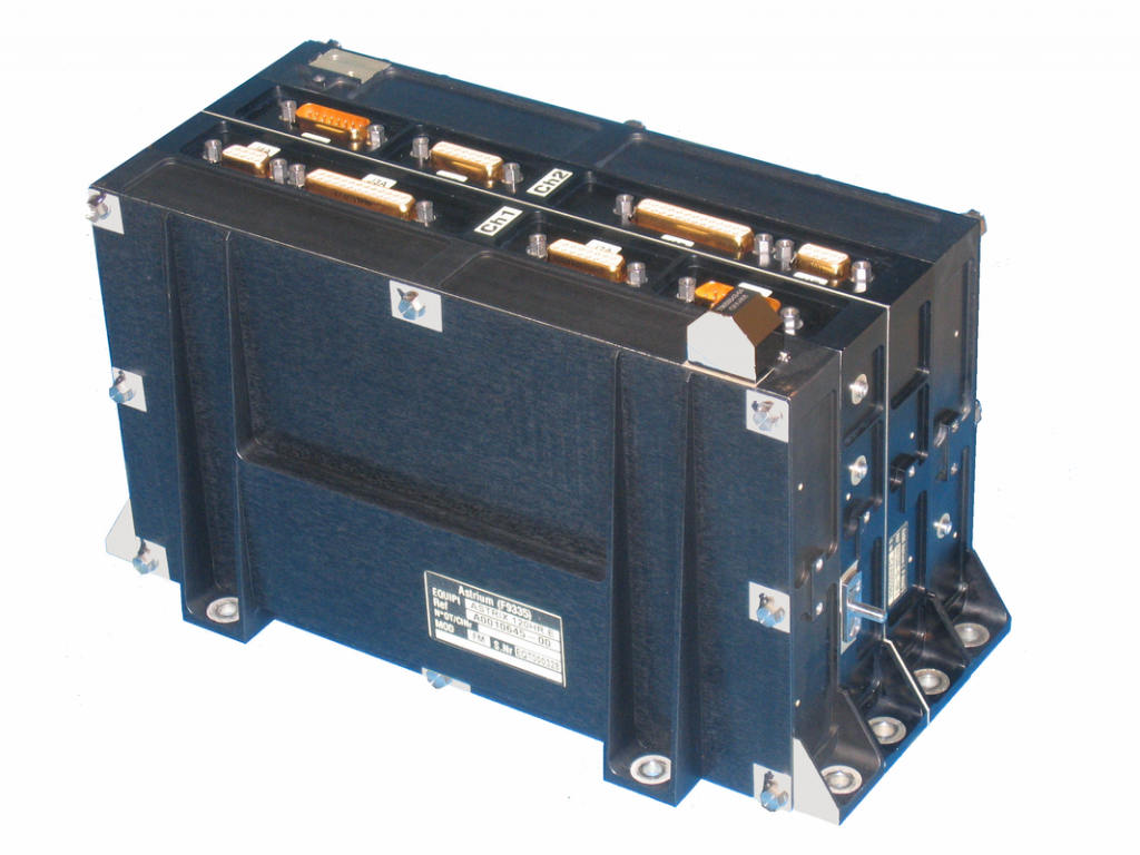
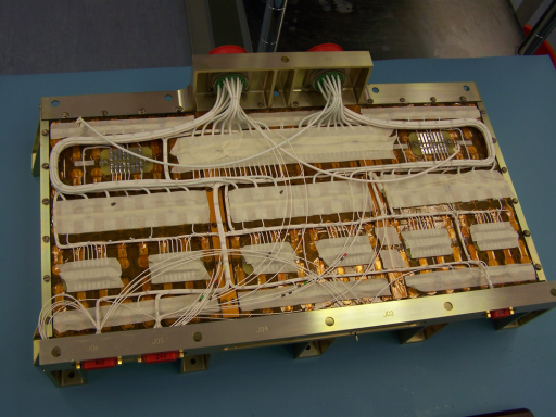
The Command & Data Management Unit controls all spacecraft functions including payload operations, communications systems, navigation equipment and the power system.
The Command & Data Management Unit, CDMU, is fully redundant and controls ground command reception and execution, on-board housekeeping operations, science data handling, telemetry formatting and transmission and attitude control and thermal control management. A built-in hot redundant fault-monitoring unit ensures a robust command architecture with in-flight reconfigurations to mitigate problems.
Gaia is outfitted with a 800-Gigabit Solid State Mass Memory that is used to store housekeeping and science data. The CDMU handles internal data transfers using a high-speed data bus that features Payload Data Handling Electronics. Data is stored and prepared for downlink in the SSMM before being transmitted via Medium and Low Gain Antennas.
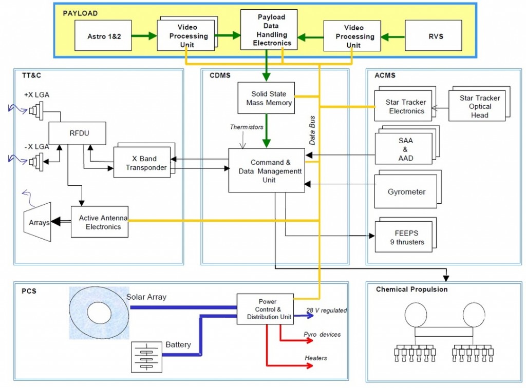
Gaia Systems Diagram
Communications System
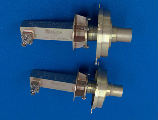
The Gaia Spacecraft is equipped with a total of three communication antennas – two Low Gain Antennas and a single X-Band Medium Gain Phased Array Antenna. One Low Gain Antenna is located pointing in the +X direction while the other points to –X being located on the Thermal Tent and the base of the spacecraft, respectively. The two Low Gain Antennas build an omni-direction communications system for housekeeping telemetry downlink and command uplink with data rates of a few Kilobits per second.
The Medium Gain Antenna is located on the base of the Payload Module, protruding the DSA. This directional antenna can achieve data rates of up to 8 Megabits per second for science data and telemetry downlink and telecommand reception.
Demodulation of the uplink signal is completed by the transponder units before the data flow is passed on to the Command & Data Management Unit. The downlink data is encoded by the CDMU and modulated in X-Band within the transponders before being amplified by the Solid State Power Amplifier. The signal is combined in the phased array of the active antenna in order to orient the beam towards the Earth.
Phased Array Antenna
Thermal Tent
Attached to the Service Module is a large Thermal Tent Structure that protects the Payload Module from thermal loads and stray light from the sun or other objects. The large cylindrical structure consists of Carbon Fiber-Reinforced Polymer (CFRP) sandwich panels. It is attached to the top floor of the Service Module.
The Tent is covered with Multi-Layer Insulation and facilitates a thermal radiator to keep the instruments at a stable temperature.
It also protects the electronics from radiation and contamination. Three openings in the tent serve as entrance apertures of the telescopes and the radiator.
Payload Module
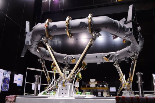
The Payload Module is mounted on the Service Module via three bipods to create an isostatic connection between the two structures. The thermal decoupling between the two modules is achieved conductively through the bipods and radiatively through the use of insulation material.
The Payload Module of the Gaia Spacecraft includes the common optical bench that facilitates the three instruments and the interface equipment that attaches the PM to the Service Module. The Thermal Tent of the Payload Module is attached to the Service Module to avoid a physical connection to the optical bench.
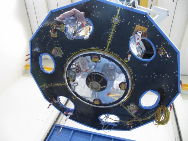
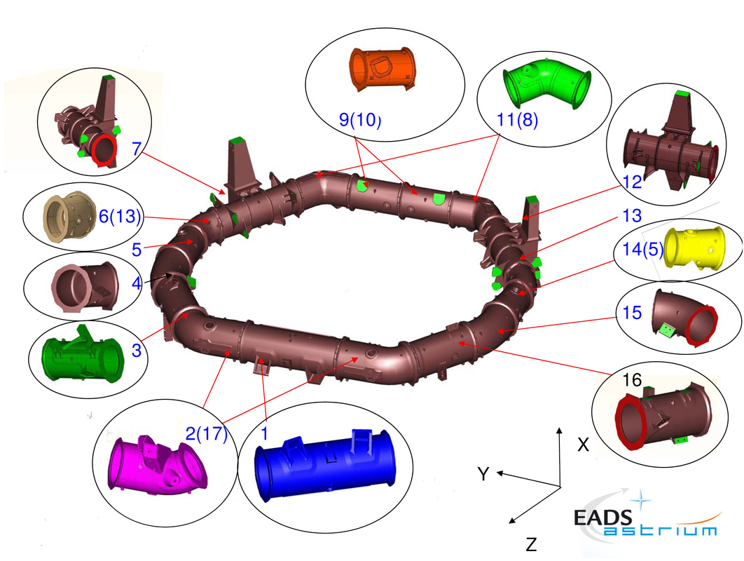
The optical bench consists of a toroidal structure that consists of silicon carbide material because of its optical, mechanical and thermal properties. The most important aspect for Gaia to meet its science objectives is a thermally stable mounting platform. This is accomplished by using silicon carbide which is known not to expand and contract as a function of temperature.
The torus is 3 meters in diameter being quasi-octagonal in structure consisting of 17 individual Silicon Carbide segments. The optical bench supports the two Gaia telescopes and the focal plane assembly.
The Gaia Spacecraft carries a payload of three instruments to complete its star-mapping mission:
- The Astrometric Instrument determines the positions of stars in the sky and provides data to track their motion and parallax
- The Radial Velocity Spectrometer determines the velocity of a star along the line of sight of Gaia using doppler shift measurements in a high-resolution spectrum
- The Photometric Instrument creates two low-resolution spectra in the red and blue range to reveal temperature, mass and chemical composition of stars