
ISS Robots successfully Replace critical Power Switching Unit outside Space Station
Robots were busy outside the International Space Station Thursday through Saturday, tasked with replacing a partially failed power switching box on the truss segment of ISS to fully restore the orbiting laboratory’s power system – sparing the crew members from venturing out on a contingency spacewalk.
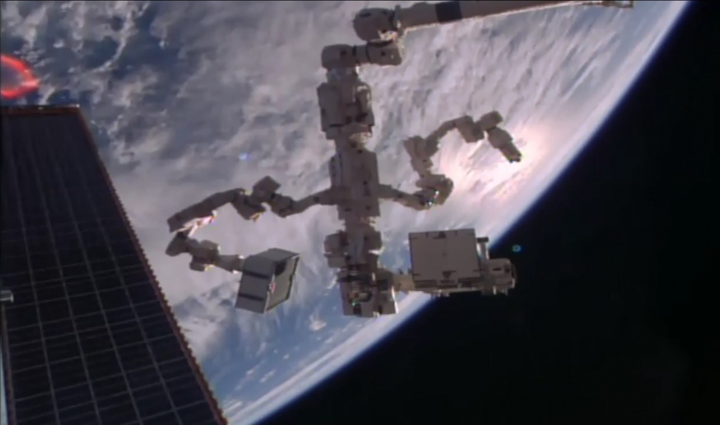
Removing and replacing one of the four critical Main Bus Switching Units (MBSUs) was a first-time activity for the Stations’ robotic duo – the 18-meter long Canadarm2 and two-armed Dextre robot. The previous replacement of an MBSU was completed back in 2012 in a two-spacewalk effort by astronauts Suni Williams and Aki Hoshide.
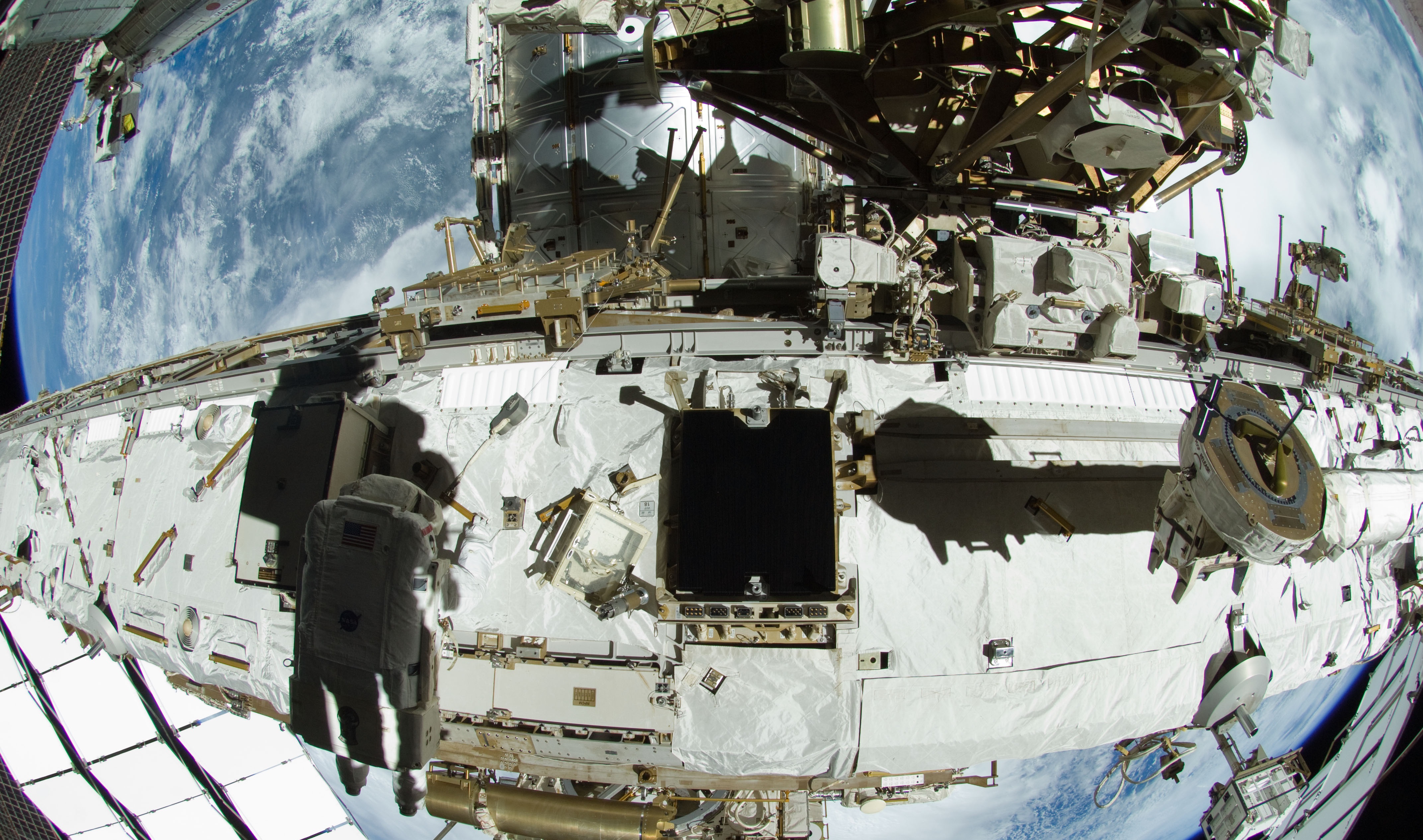
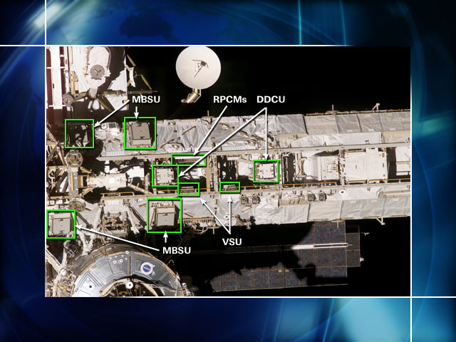
The Main Bus Switching Units are a critical part of the Space Station’s power system, acting as a central distribution hub between the solar power generators and the various internal and external power-consumers on ISS.
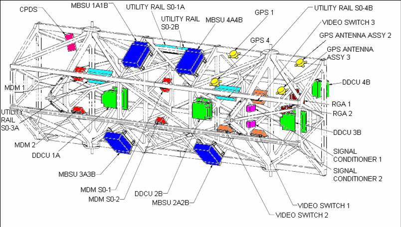
The Station’s four MBSUs all reside on the central S0 Truss and each accepts primary power from two of the station’s power channels which it then distributes downstream to direct-current converters that create the secondary power flow to the various users. MBSUs can be cross-tied to re-wire the Station’s power system architecture in the event of an upstream failure.
The recent MBSU issue manifested on April 25, 2017 when MBSU #2 suffered an unexpected Loss Of Communications. Mission Control was unable to command the MBSU and no status telemetry was received from the unit, however, MBSU #2 continued to pass power from the 2A and 2B power channels to the downstream DC-to-DC Converter Units (DDCUs). Although the fault had no immediate consequences such as system power-downs, a loss of commanding and telemetry is considered a serious anomaly that sets in motion a series of steps on the ground to assess recovery options.
One of the first steps taken by the ground team is evaluating the ‘next worst failure’ to establish impacts on ISS and its crew in case another component within the Electrical Power System failed. This was determined to be MBSU #2 failing to transmit power altogether which would have required the crew to put in place contingency jumpers to keep all of the Station’s critical systems powered via the three remaining MBSUs.
Looking into the failure signature, engineering teams noted the Loss of Communications issue closely resembled a similar problem observed on MBSU #1 in 2011/12 which required replacement of the MBSU via EVA. Meetings were held to evaluate forward options and it was decided to give the Station’s robots the first shot at replacing the partially failed unit with a potential spacewalk kept as an option should the robots run into problems.
The timing of the replacement operation was advantageous as preparations for a scheduled spacewalk on May 12 are currently underway, meaning the addition of a second EVA, had it been needed for the MBSU, would not be as time-consuming as starting the EVA preparation process from scratch.
The MBSUs, aside from MBSU #1 that was replaced in 2012, have been installed on the S0 truss segment ever since being delivered by Space Shuttle Atlantis in 2002 – all four were activated in 2006 as part of work completed during the STS-116 Shuttle mission. Built for a design life of 15 years, the MBSUs are right now reaching the end of what could be expected to be a trouble-free life and effects of aging would no-longer be a surprise going forward.
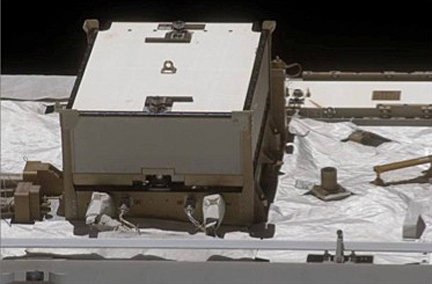
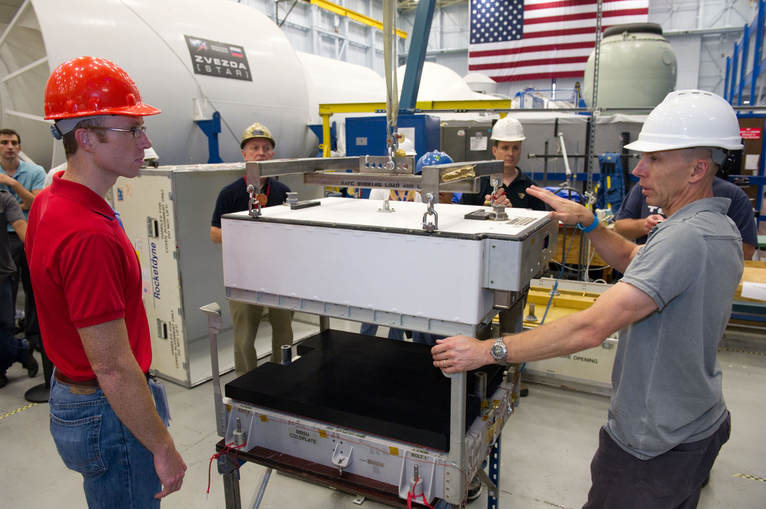
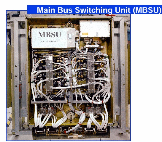
The MBSUs are rather sizeable Orbital Replacement Units, measuring 71 x 101.6 x 30.5 centimeters in dimensions and weighing 99.8 Kilograms. Internally, the unit comprises Remote Bus Isolators as part of a pair of Bus Bar Assemblies, each with a Current Sensor Assembly and a central control network. A Switchgear Controller Assembly is responsible for commanding the MBSU, monitoring its health and transmitting status telemetry – SCA is the primary suspect in the failure of MBSU #2.

The 2011 failure of MBSU #1 was believed to have been caused by radiation hits to the unit’s memory unit within the controller assembly. After the initial signature of degradation, the MBSU continued to pass power and intermittent telemetry, providing occasional insight into its status.
This allowed teams to take their time planning an EVA effort, eventually put in motion in August 2012 when Williams and Hoshide stepped outside on what was expected to be a single EVA to replace the MBSU with an in-orbit spare. However, the two spacewalkers encountered significant issues with the two structural bolts holding the MBSU in place – spending several hours battling with the bolts. A second EVA had to be added to finish the replacement effort and the crew was sent outside with makeshift tools to clean up metal filings created by the jammed bolts, but efforts eventually paid off and the Station’s power system was restored.
For MBSU #2, the Station’s robots got the first attempt at the replacement, showcasing a growing confidence in the abilities of the Dextre robot and ROBO specialists at Mission Control.
Over the course of the Station’s early life, any external failure was cause for a spacewalk, but over recent years, the Station’s robots have taken on more and more maintenance tasks outside ISS, enabled by a series of tools given to the Dextre robot to remove, handle and install different-sized Orbital Replacement Units. Dextre was first used as an external repairman in 2011 when switching a broken circuit breaker – back then a two-day activity.
Some tasks have become routine – like last week’s replacement of a circuit breaker box on the Station’s truss – while other tasks mark first-time activities – such as the battery replacement accomplished earlier this year in a human-and-robotic effort.
The MBSU replacement only became part of Dextre’s repertoire in early 2016 after an exercise demonstrated the robot could remove a spare MBSU from its Flight Releasable Attachment Mechanism.
This activity revealed a number of smaller challenges associated with maneuvering the unit and loads during the extraction of the unit – delivering valuable lessons that undoubtedly came in handy during this week’s operation.
Thursday accomplished all major prerequisites inside and outside ISS to set up for the actual MBSU replacement procedure running from Friday afternoon (UTC) into the early hours on Saturday.

Controllers on the ground tied five of the seven DC converters fed by MBSU-2 to another MBSU while the remaining two DDCUs (LA2B & S02B) had to be manually connected by the crew by installing a pair of jumpers inside the U.S. Lab module, known as the Lab Secondary Power Distribution Assembly (SPDA) Jumper to power the LA2B power bus and the Lab Truss Contingency Jumper (LTCJ) to power half of the Station’s external cooling system.
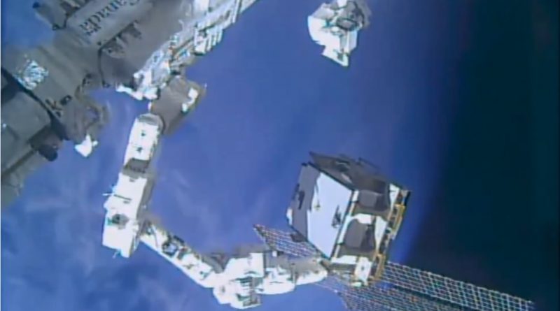
Outside ISS, Dextre was moved over to External Stowage Platform (ESP) 2 where two spare MBSUs resided – one delivered by STS-120 in 2007 and the other flown up on the HTV-4 spacecraft in 2013. The MBSU, along with its Flight Releasable Attachment System (FRAM) was transferred to Dextre’s Enhanced ORU Temporary Platform (EOTP) side 2 – essentially a holding platform that allows Dextre to hold onto ORUs while keeping its two arms free for other operations.
The last item on Thursday’s task list was breaking torque on the two structural bolts of the spare MBSU to ensure an easy removal.
The actual replacement work began Friday afternoon when Mission Controllers completed the final reconfiguration of the electrical system by powering down a number of systems in the U.S. Lab and Node 3. Robotics were handled by controllers in Houston and at the Canadian Space Agency’s Saint Hubert facility.
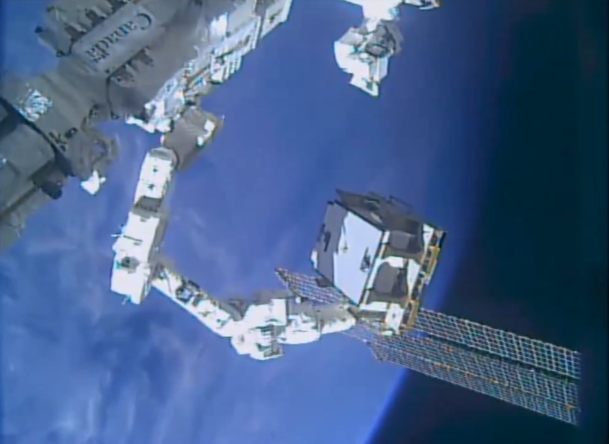
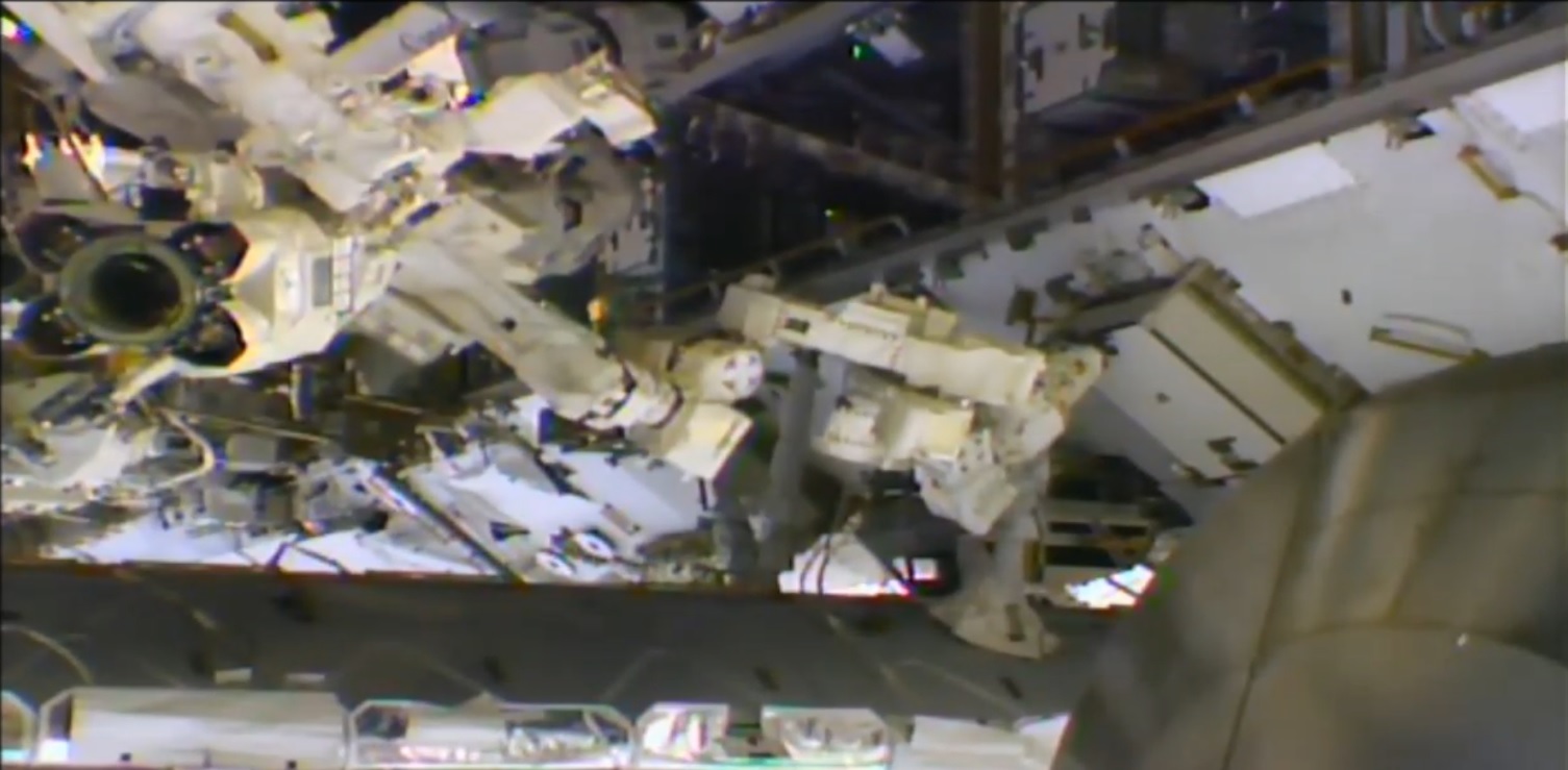
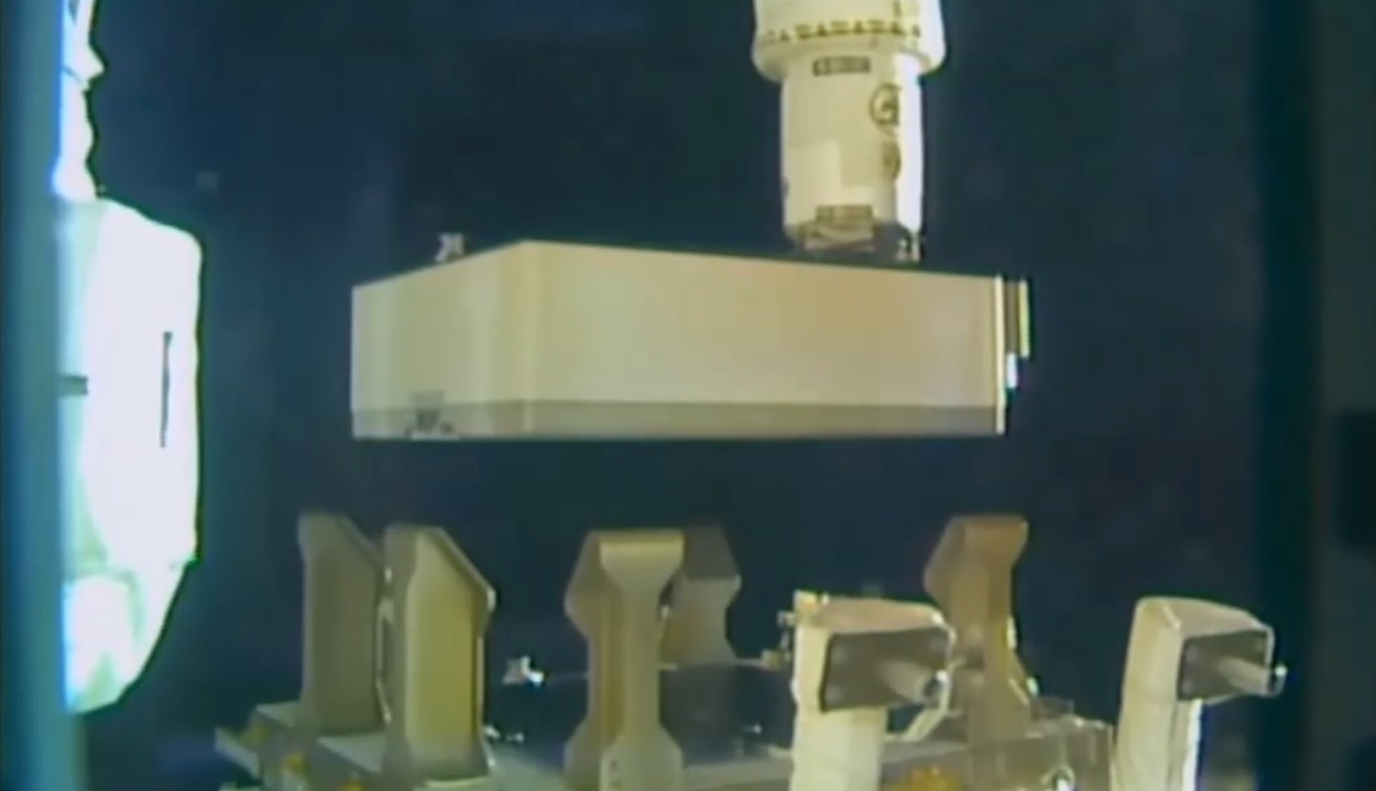
For the replacement, Dextre employed its ORU Tool Changeout Mechanism (OTCM) and Robotic Offset Tool (ROST) to remove the partially failed MBSU by releasing the H1 secondary bolt followed by the H2 primary bolt which enabled the robot to pull the MBSU away from its coldplate, in the process disconnecting blind-mate electrical/data interfaces.
Next, Dextre used its other arm to retrieve the spare MBSU from the EOTP by also releasing its two strucutral bolts and pulling the unit from its FRAM. The robot then rotated around to properly position the spare unit for installation – using guide-rails to enable blind-mate connectors to engage when the MBSU reached its soft-docked position on its coldplate. Dextre the drove the H2 primary bolt followed by the secondary bolt to fully secure the new MBSU in position, allowing Mission Controllers to flow power to the unit and check its status.
The removed MBSU was installed on the empty FRAM and Dextre went on a ride on Canadarm2, moving over to ESP-2 where the FRAM was put in its original place. Future plans for the failed MBSU are likely disposal via Japan’s HTV spacecraft or the SpaceX Dragon – both of which are equipped to ferry Orbital Replacement Units to the Space Station. At present, ISS has one fully functional MBSU as a spare.
With ROBO operations reaching a successful conclusion, Mission Controllers were able to power up the MBSU and initial checks showed it was healthy. Early on Saturday, reconfigurations were made to begin transitioning DDCUs back to the MBSU and the crew was told Node 3 and Lab Systems were back in their original configuration. Moving the External Thermal Control System back to MBSU #2 will require a temporary power-down of ETCS Loop B – to be completed in the coming days to fully restore the station’s power configuration.
Big Picture: MBSU’s Role in the Space Station Power System
The Main Bus Switching Unit is a critical component of the Space Station’s Power System that is required to distribute power from the Solar Arrays and Batteries to other electrical components before reaching the modules and users. The ISS electrical power system consists of power generation, energy storage, power management and distribution equipment – short: PMAD.
All USOS (United States Orbital Segment) power is generated by the Space Station’s eight Solar Array Wings that build the photovoltaic electric power generation subsystem consisting of eight power channels, one for each array.
One PV Module (Photovoltaic Module) consists of two solar array wings – each wing being 35 meters long and 12 meters wide. There are 32,800 solar cells on each power channel, 400 of those are connected in series to form a string with 82 strings connected in parallel. Six channels use Nickel-Hydrogen batteries for power storage while two channels have been upgraded with Li-Ion battery units. The batteries are charged when the Solar Array Wings are exposed to sunlight and are discharged when the Station is making a night-pass or when additional power is required on-board.

When in sunlight, the Solar Arrays are continuously pointed at the Sun by computer controlled sun tracking capabilities that are realized by one Beta Gimbal Assembly located on each PV Module that rotates the wing, while a single Solar Alpha Rotary Joint is used to rotate four arrays on one side of the truss to follow the Station’s orbital motion.
Before power generated by the Solar Arrays enters the rest of the electrical system, it has to pass Sequential Shunt Units (SSU) that regulate the power coming from the arrays at an established setpoint of 160 volts.
Responsible for managing the primary power coming from the Solar Arrays (actually from the SSUs) are Direct Current Switching Units – DCSUs – which control initial power distribution.
During orbital day, the eight DCSUs send a portion of the primary power to the Station’s MBSUs to go to the users while the other portion of the primary power is transferred to BCDUs – Battery Charge/Discharge Units that control the charging and discharging of each of the batteries – managing the available battery power.
During night passes when no new power is generated by the solar arrays, power is sent from the Battery Charge/Discharge Units back to the Direct Current Switching Units which then pass it along to the Main Bus Switching Units. Space Station primary power operates at a voltage range of 137 to 173 volts direct current.
There are four Main Bus Switching Units aboard the Space Station, all of them are mounted on the S0 Truss Segment and each one is fed power from two of the power channels. So, MBSU-1 receives power from channels 1A and 1B, while MBSU-2 receives primary power from channels 2A and 2B, and so on. Both, MBSUs and DCSUs use a network of high power switches to direct the power flow. These are called Remote Bus Isolators, RBIs. RBIs are used to isolate power path and distribute loads to other channels in case of failures. The RBI network is controllable from the ground and by on-board computers.
Each MBSU distributes power from its two associated channels further downstream where conversion to secondary power occurs. DC to DC Conversion Units, DDCUs, convert ISS primary power to a stable 124.5V DC power supply for all other EPS components. One final component in the EPS string are Remote Power Control Modules (RPCM) which contain circuit breakers. From the RPCMs, power is routed to equipment of the Space Station.
MBSUs also route primary power to the Russian Service Module, where equipment is located that is needed to integrate the Russian System which is working with 28V DC power into the USOS power supply. At the Service Module, primary power is converted to Russian Secondary Power via the American to Russian Conversion Units (ARCUs). Power provided by the ARCUs is then routed inside the Russian Segment to users requiring the 28V DC bus voltage. There are also Russian to American Converter Units (RACUs) for the reverse conversion process as a backup.
MBSUs are also an essential part of the flexible ISS Electrical Power System Architecture. The Main Bus Switching Units can be cross-tied in the event of equipment failures upstream, allowing all MBSUs to pass power and fully support loads should one power channel fail. This greatly enhances the failure tolerance of the EPS, but places priority on the MBSUs: in case of a failed MBSU, there is no option of keeping all power channels alive, requiring power downs and cross-ties at the DDCU level.