
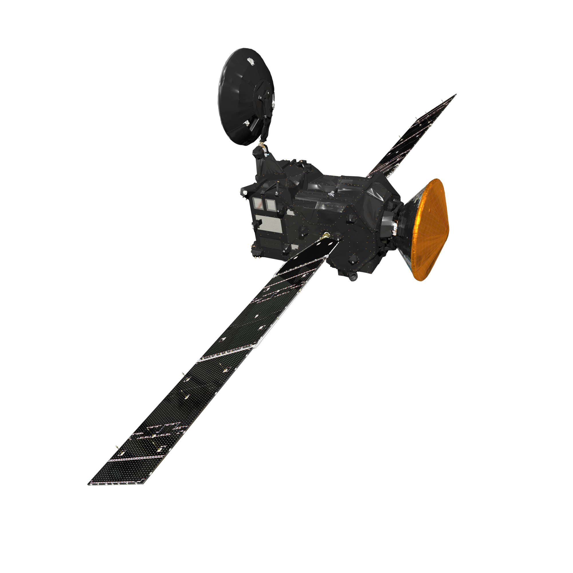
Trace Gas Orbiter
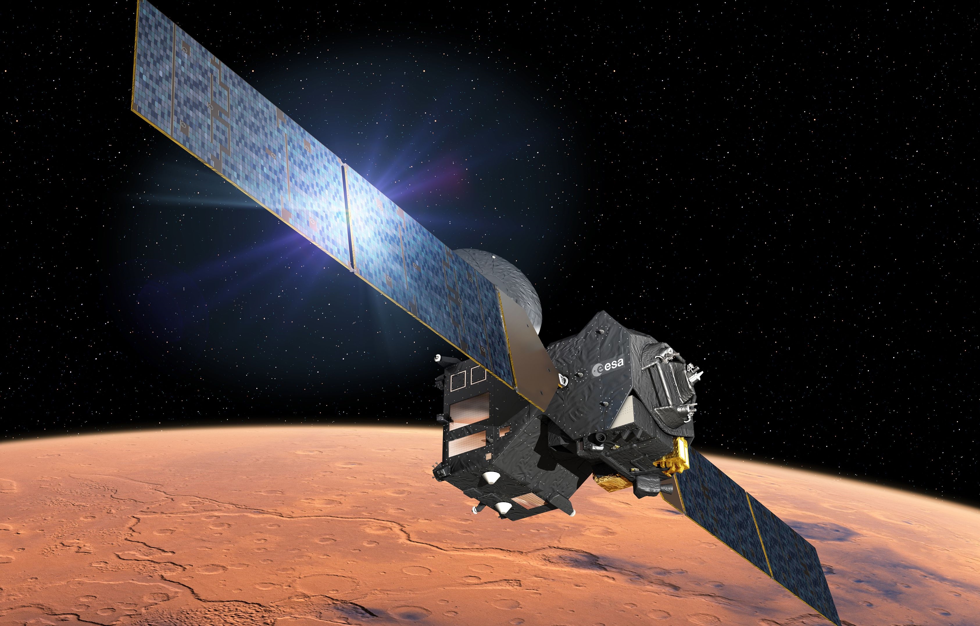
The Trace Gas Orbiter (TGO) is the principal component of the ExoMars 2016 mission, setting out for a multi-year exploration mission in orbit around Mars to map the Martian atmosphere with special focus on trace gases including Methane, a biologically relevant gas that has shown a spatial and temporal variability making its sources and sinks an interesting topic of study.
TGO was built by Thales Alenia Space under contract by the European Space Agency and carries four instruments, two developed in Europe and two contributed by Russia in the mission’s collaboration between ESA and Roscosmos.
Spacecraft Structure
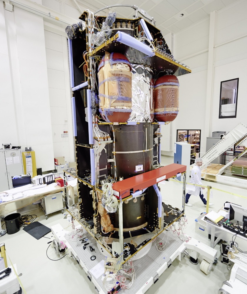
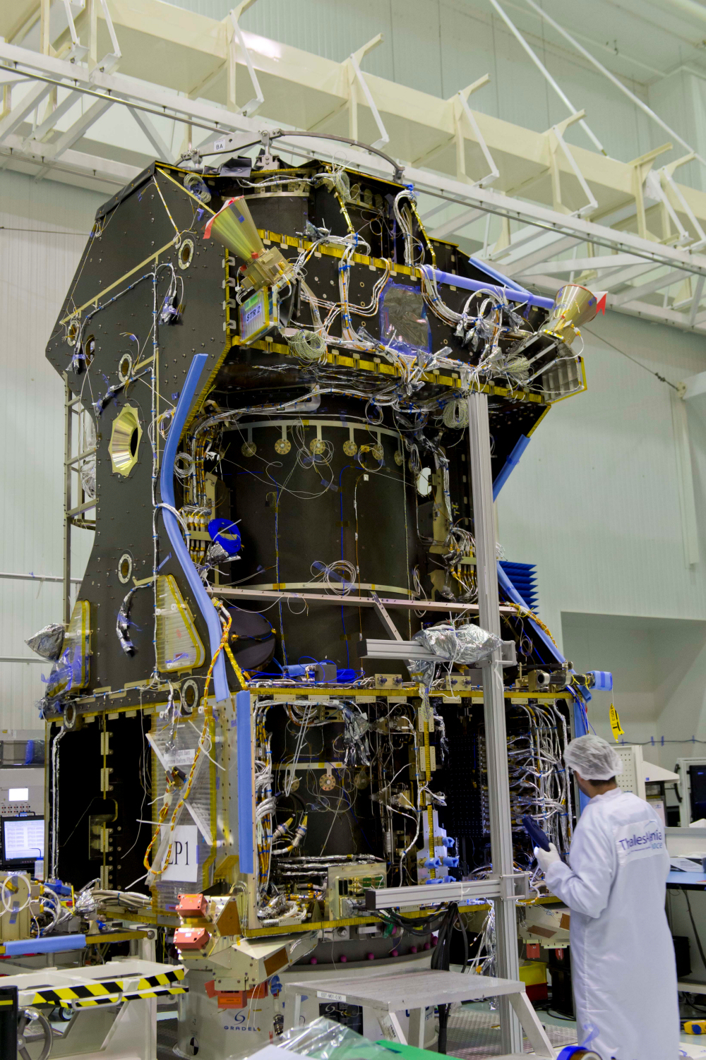
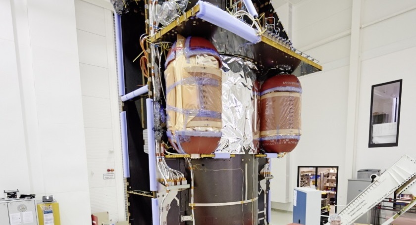
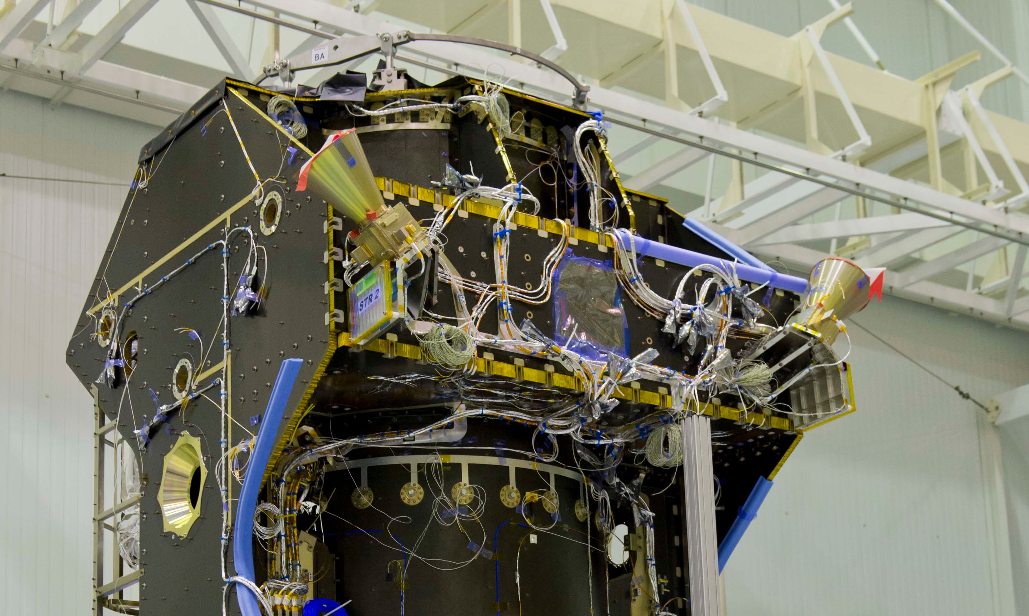
The Trace Gas Orbiter is comprised of a box-shaped spacecraft platform supported by an interior central tube 1.19 meters in diameter. In its launch configuration, TGO measures 3.2 by 2 by 2 meters and has a mass of 4,332 Kilograms including the 112-Kilogram science payload and 600-Kilogram Schiaparelli lander that is being ferried to Mars by the orbiter and released on an intercept path with the Planet three days before arrival.
Structurally, TGO is comprised of the Central Tube supporting the satellite structure, internal panels fanning out from the central tube and external panels, providing mounting surfaces for the various orbiter subsystems. The internal and external panel use a Carbon Reinforced Polymer – Aluminum Honeycomb material taking advantage of its stability and low weight.
The central cylinder serves as a backbone of the spacecraft, distributing loads experienced during launch throughout the spacecraft structure. It also provides a base for the attachment of the Schiaparelli lander on the zenith side of the spacecraft. The propellant tanks are facilitated within the central tube to allow the center of gravity of the vehicle to remain in one place when the tanks are emptied.
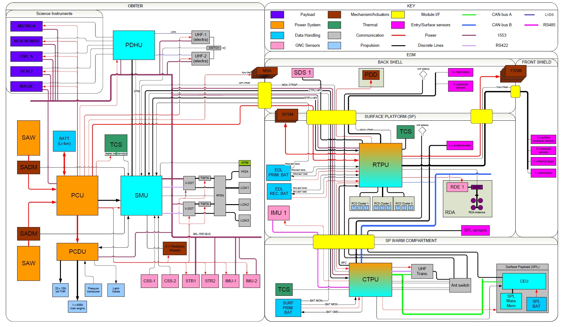
Spacecraft Block Diagram
Electrical Power System & Thermal Control

For power generation, TGO is outfitted with a pair of solar arrays that will measure 17.5 meters from tip to tip when deployed in space. Covered with triple-junction Gallium-Arsenide solar cells, each array is comprised of two panels, being 3.12 meters long and 1.74 meters wide, bringing the length of each array to 7.9 meters. On average, the solar arrays will generate 2,000 Watts of power, delivered to the Power Conditioning Unit (PCU) that conditions the spacecraft’s regulated power bus and controls the state of charge of the spacecraft battery. Each solar array has its own Solar Array Drive Mechanism capable of rotating the solar arrays to continuously face the sun whenever possible given the spacecraft’s orientation.
The PCU delivers nine separate and redundant power lines that are individually protected for maximum power flexibility and robustness of the system. The PCU directly delivers power to the Propulsion Control and Drive Unit, a separate line delivers power to the Spacecraft Management Unit and the Attitude Determination and Control System.
The remaining power lines pass electrical power to the instruments, the Payload Data Handling Unit, the UHF Electra Radios and the Thermal Control System. Furthermore, separate power lines are provided to the Pyro Bus and the Schiaparelli lander to keep the lander’s non-rechargeable batteries charged until separation by having the lander rely on TGO’s power during cruise.
TGO makes use of a pair of rechargeable Lithium-Ion batteries to deliver electrical power when passing through eclipse or during periods of increased power demand. The batteries have a total capacity of 5100 Watt-hours.
For Thermal Control, TGO relies on a combination of active thermal control systems as well as passive systems. Passive thermal control is accomplished with thermal coatings and multi-layer insulation blankets to keep components above their critical survival temperatures. The active part of the TCS is comprised of a series of thermistors that deliver temperature readings to the Spacecraft Management Unit which then commands heaters on-and-off to maintain safe temperatures for critical subsystems.
Propulsion System
The Trace Gas Orbiter hosts a main propulsion system and a propulsive attitude control system to stabilize its orientation, adjust its course towards Mars, insert itself into orbit around the Red Planet and make orbit correction maneuvers over the course of its mission. The propulsion system is comprised of an S400-15 main engine for large maneuvers and two banks of ten thrusters for attitude maneuvers and fine-tuning maneuvers.
All thrusters use Monomethylhydrazine as fuel and Mixed Oxides of Nitrogen as oxidizer, stored in two cylindrical tanks that are mounted atop each other inside the central tube of the satellite. Each tank has a capacity of 1,207 liters and TGO launches with around 1,000 Kilograms of fuel and 1,500kg of oxidizer on board. Two Helium tanks are installed outside the central tube, holding high-pressure Helium gas at 310 bar to be delivered to the tanks for pressurization.
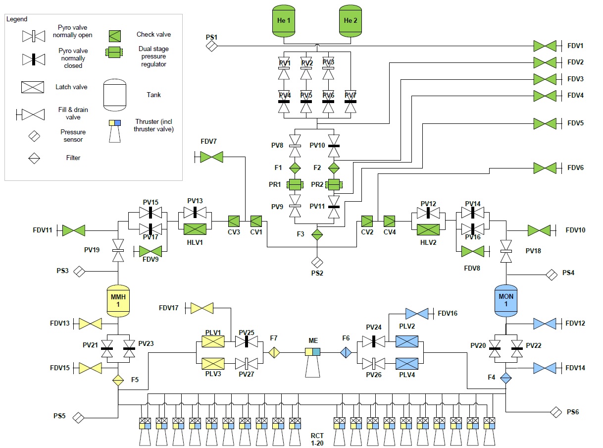

The Helium pressurization system includes several pyrotechnic valves, filters, check valves, pressure regulators and pressure transducers to ensure Helium is delivered to the tanks at the correct pressure. Directly downstream from the He tanks is a pyro valve system with four lines, three of which can be opened and closed by firing separate valves in order to be able to re-pressurize the propulsion system at three points in the mission. A fourth valve can be used to initiate an irreversible pressurization.
This pyrovalve ladder is used to isolate the pressurization system between main engine firings in order to minimize the time the system is at high pressure and subjected to internal leakage.
The pressurant then passes through filters and dual-stage pressure regulators in a redundant setup before the helium line is divided in two segments one leading to the MMH tank, the other to the MON tank. Each line includes a pair of check valves, a latch valve, pyrotechnic safety valves and pressure transducers.
Propellants are fed from the tanks to the main engine and the two reaction control thruster banks through separate lines. The lines include propulsive valves for isolation and pressure sensors to keep track of line pressures. Each of the Reaction Control Thrusters has redundant propellant valves and the main engine supply line is outfitted with pairs of latch valves and isolation valves as well as propellant filters.
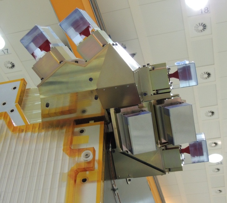
Two banks of ten Reaction Control Thrusters are installed on the Trace Gas Orbiter, each bank comprised of thruster clusters with engines facing different directions to enable the system to deliver three-axis attitude control.
The thrusters are arranged in three sets – Set A comprised of four thrusters on the -X-side of the spacecraft without any cant angle to be used in delta-V maneuvers and to deliver torque along Y and Z; Set B using 4+4 thrusters with a 70° cant angle to deliver roll control and X torque, and Set C for force compensation with 2+2 thrusters installed on two opposite corners on the -X face with 60° cant angles towards +X.
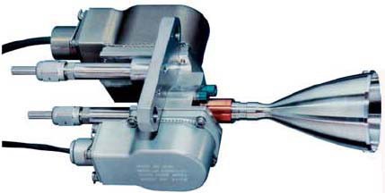
The S10-18 10-Newton thrusters are manufactured by Airbus Defence and Space consisting of a platinum alloy combustion chamber and nozzle that tolerates the operational temperature of 1,500°C. The thruster can be operated in a thrust range of 6 to 12.5 Newtons with a nominal thrust of 10-Newtons which generates a specific impulse of 291 seconds.
It operates at an inlet pressure of 10 to 23 bar and a chamber pressure of 9 bar – for TGO, the typical inlet pressure will be 11 bar.
The engine operates at a nominal propellant flow rate of 3.5 grams per second and a mixture ratio of 1.65 with a possible range of 1.2 to 2.1. The thruster has a throat diameter of 2.85mm while the engine nozzle is 35mm in diameter and has an expansion ratio of 150. The 10N thruster has a qualified accumulated burn life of 70 Hours with up to one million duty cycles.
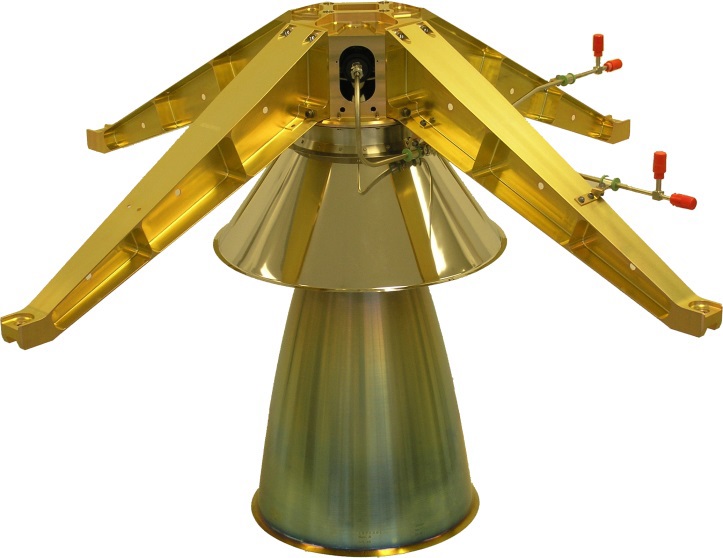
As main engine, TGO uses an S400-15 thruster, also manufactured by Airbus Defence and Space and specially qualified for long single burns as well as high cumulative burn time to meet the requirements for an interplanetary mission. S400-15 delivers a nominal thrust of 424 Newtons at a specific impulse of 330 seconds.
Attitude Determination & Control
The Attitude Determination and Control System of the Trace Gas Orbiter consists of a pair of star trackers, two Coarse Sun Sensors and two inertial measurement units for attitude determination and four Reaction Wheels plus the Reaction Control Thrusters for attitude actuation.
Two wide-angle star trackers are used to acquire imagery of the sky analyzed by a software algorithm that compares the acquired star pattern with a catalog to precisely determine the spacecraft’s orientation in space. The star trackers are connected to the 1553 data bus to relay precise attitude data to the vehicle’s control system.
The Star Trackers have a field of view of around 20 x 20 degrees and can track up to 15 stars to calculate the spacecraft’s orientation from a lost in space scenario in under ten seconds. Each Star Tracker assembly weighs 2.6 Kilograms including a 26° Sun Exclusion Angle Baffle. Overall, the Star Tracker achieves an accuracy of 8.3 arcsec on the pitch & yaw axes and 11 arcsec along the roll axis.

Two Coarse Sun Sensors are used by the Trace Gas Orbiter to calculate the solar vector for sun-pointing of the solar arrays and attitude control in spacecraft safe modes. Each Coarse Sun Sensor weighs a little over 200 grams and measures 12 by 13 by 3 centimeters in size with a field of view of +/-35° on x and +/-65° on the y axis. Typically, the CSS achieves an accuracy of +/-2° in determining the sun’s position using radiation hardened detectors and protective cover glass.
In addition to its optical attitude sensors, the Trace Gas Orbiter relies on two Inertial Measurement Units to measure body rates along all spacecraft axes and track acceleration during engine firings. Each IMU consists of a 3-axis Ring Laser Gyro and 3-axis accelerometer. The system uses the basic principle that counter-propagating laser beams have different frequencies with the difference dependent on rotation rate which can be measured to calculate the rotation rate about the RLG’s sensitive axis.
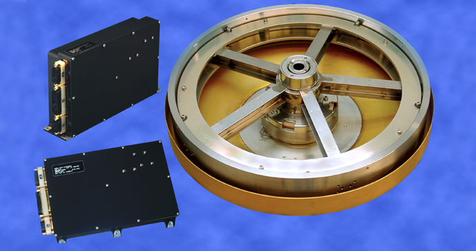
Attitude actuation is provided by a Reaction Wheel Assembly comprised of four wheels for redundant attitude control along all three axes. The reaction wheel assembly is a rotating inertial mass that is driven by a brushless DC motor that spins the wheel. When accelerating the wheel, the satellite body to which the wheels are directly attached will rotate to the opposite direction as a result of the introduced counter torque. Because the wheels have to be de-spun regularly, the thrusters are needed to deliver counter-torques to keep the spacecraft in a stable orientation.
The Reaction Wheels deliver an angular momentum of 23Nms spinning at up to 7,500 RPM. The wheels are 35 centimeters in diameter and measure 12cm in height with a mass of around 5 Kilograms. Control of each wheel is accomplished with a Wheel Drive Electronics Unit connected to the Spacecraft Management Unit to execute attitude commands.
The main controller of the Attitude Determination and Control System is the Propulsion Control and Drive Unit that interfaces directly with the Spacecraft Management Unit and all propulsion system components as well as the 1553 data bus interfacing with the attitude determination system. The PCDU is commanded by the Spacecraft Management Unit based on the current mode of spacecraft operation.
TGO can utilize five different Attitude Control Modes:
Sun Acquisition Mode: The SAM mode only uses data from the Coarse Sun Sensors and Inertial Measurement Unit to calculate the spacecraft’s relation to the sun and use the Reaction Control Thrusters to re-orient the spacecraft to its sun-pointing attitude. This mode is used immediately after separation from the launch vehicle and in spacecraft safe mode. SAM is available with spin-stabilization around the Z-axis. During eclipse periods, the spacecraft attitude is propagated through the use of gyro data.
NOMP – Nominal Mode using Propulsion: This attitude mode uses the star trackers, Inertial Measurement Unit and Reaction Control Thrusters to keep the spacecraft three-axis stabilized. It is used to acquire a commanded attitude target from any given orientation and is typically used after temporary loss of star tracker data. It is also used during Earth pointing recovery in Safe Mode and when high control authority is required (during EDM release).
NOMR – Nominal Mode using Reaction Wheels: This control mode delivers fine 3-axis pointing mode based on Gyro-Stellar attitude frames with use of the reaction wheels for routine pointing. This attitude mode is normally used during the science phase and the exospheric segments in the Aerobraking phase. Unloading of the reaction wheels can be autonomously completed by the spacecraft in the NOMR mode.
OCM – Orbit Control Mode: This mode of attitude control is utilized for maneuvers with the main engine or Reaction Control Thrusters depending on the required delta-v. This mode uses the accelerometers to track the delivered delta-v, the gyros and star trackers for attitude determination and the thrusters for attitude control. Boost-stop triggers can be based on timed commands or accelerometer readings.
AEBM – Aerobraking Mode is used when the spacecraft skims the upper atmosphere of Mars to change its orbit, employing rate dampening around the aerodynamic equilibrium attitude. It uses the Inertial Measurement Units for body rate measurements and the thrusters for actuation.
Command & Data Handling
The Command and Data Handling System of the Trace Gas Orbiter is separated in general spacecraft-related tasks and a dedicated system for payload data handling.
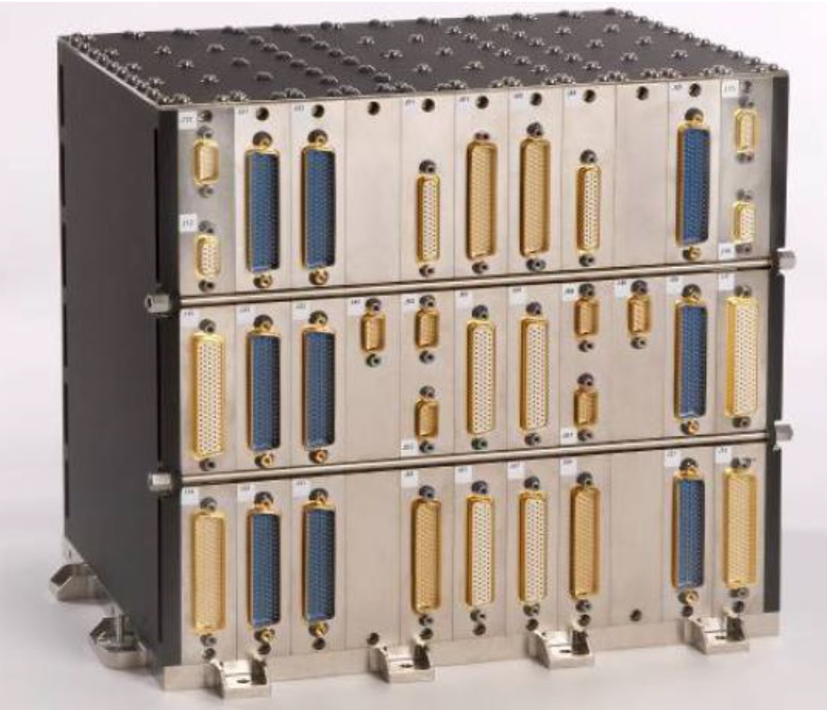
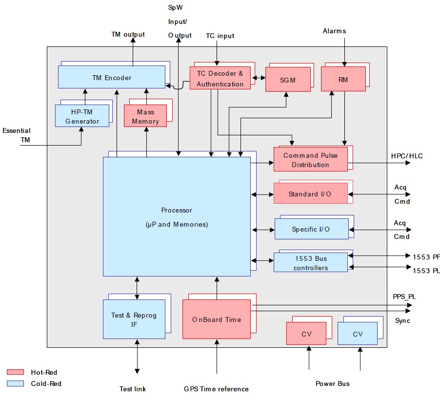
The brain of the TGO spacecraft is the Spacecraft Management Unit that interfaces with all spacecraft subsystems and is in charge of accepting and executing commands sent from Earth according to specified command times, controlling all spacecraft subsystems and processing telemetry from the different systems to deliver housekeeping data to the ground. The SMU is a redundant computer comprised of different slices serving a specific purpose and interconnected within the SMU, each slice being present twice for internal redundancy.
The SMU is built around a central processor and includes standard and specific input/output cards, 1553 data bus controllers, onboard timers, test links, power bus controllers, command pulse distributors, fault detection systems, telemetry/command encoders and decoders, mass memory units, and a number of other components.
Specific tasks of the SMU include telecommand reception, decoding and handling; telemetry transfer frame generation, coding and modulation for downlink; timing synchronization; mass memory storage for telemetry data; monitoring and control of spacecraft equipment; commanding of the Solar Array Drive Mechanisms, Power Control Unit, Propulsion Drive and Control Unit, and Payload Data Handling Unit. Another important function of the SMU is Mission Time Line management to be able to execute commands based on time-tags requiring synchronization of timelines used on the ground and aboard the spacecraft.
SMU completes commanding of spacecraft systems based on mode types different for the various mission phases from launch, through coast and deep space maneuvers, to orbital insertion, aerobraking and nominal science operations. Mode transitions can be completed according to a smart onboard logic, time-tagged commands and directly through ground commanding. Commands from the ground are put through an autonomous verification process to ensure they are acceptable for the current mission mode.
TGO employs autonomous Failure Detection, Isolation and Recovery to switch to redundant systems in case of single-point failures to maintain all spacecraft functions without interruption. The SMU runs application software for Guidance, Navigation and Control, Thermal Control, capable of switching to compatible software versions for different mission phases and autonomously accounting for changes in spacecraft characteristics such as mass and inertia after EDM separation.
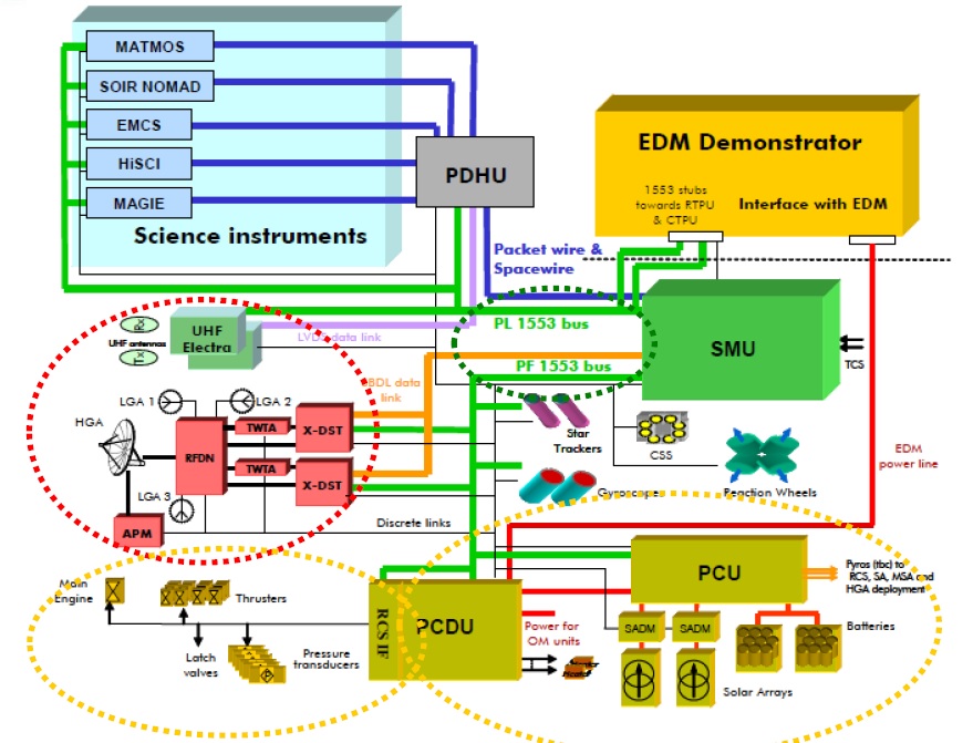
The Payload Data Handling Unit interfaces with the five instruments of the spacecraft and the two Electra UHF radios via a 1553 data bus for commanding and housekeeping data transfer and a high-speed SpaceWire bus for instrument data transmission. A Low Voltage Differential Signaling line connects the PDHU and the Electra radios, the PDHU interfaces with the Spacecraft Management Unit via 1553, Spacewire and discrete links.
The PDHU is in charge of collecting data from the science instruments, the EDM lander and the rover (via Electra). It also stores instrument, EDM and rover data in a redundant mass memory with a 128-Gbit storage capacity. Furthermore, the PDHU is in charge of storing data from Earth and relaying it to the ExoMars rover using the Electra radio.
Stored within the Mass Memory of the PDHU are received packets from the EDM lander, packets uplinked from the rover, commands and data to be downlinked to the rover, and data from TGO’s instruments which is downlinked on a daily basis.
Communications System
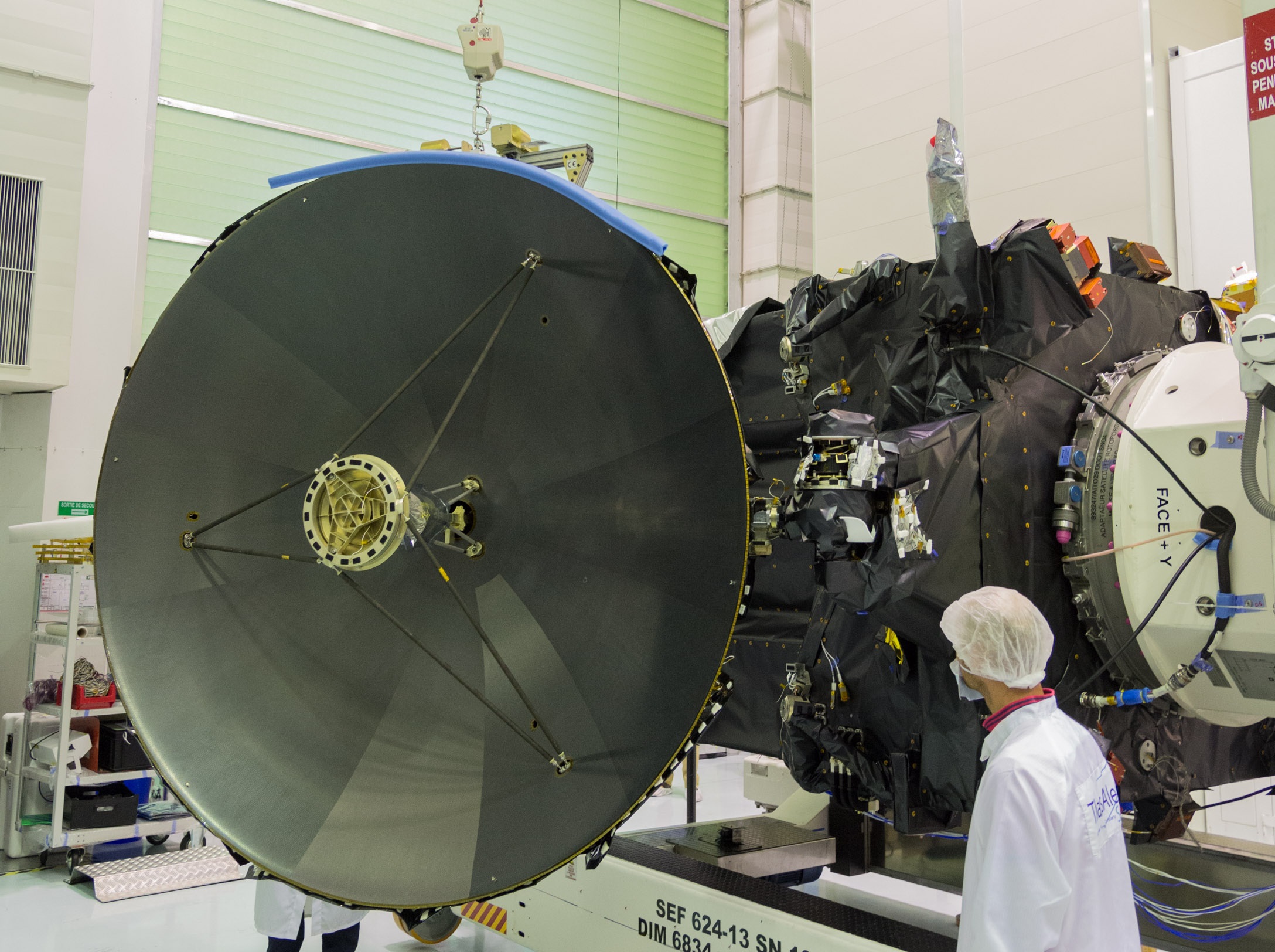
The Trace Gas Orbiter combines a high-rate communications system with omni-directional low-gain communications to keep in touch with the ground for command uplink and the downlink of science and housekeeping data.
The spacecraft is outfitted with a 2.2-meter parabolic High-Gain Antenna fed by an X-Band system comprised of redundant X-Band transponders, switches and 65-Watt Traveling Wave Tube Amplifiers. The three Low Gain Antennas are fed by the same X-Band system to receive and transmit low-rate data.
Typically, TGO transmits real time housekeeping telemetry to the ground during critical mission phases. As part of the nominal mission such as the science phase, TGO downlinks playback telemetry and science data stored in the mass memory during scheduled communication slots.
Electra UHF Radio
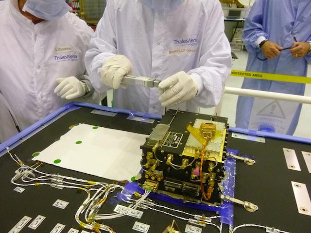
The Trace Gas Orbiter is outfitted with a pair of Electra UHF radios provided by NASA to serve as an orbital communications terminal – relaying commands from the ground to NASA and ESA rovers on the surface and accepting data from the rovers to be relayed to Earth using the high-speed data links of the orbiter.
Electra has been used on a number of previous Mars missions and has become the standard system used to relay data from Mars rovers.
The Electra terminal consists of dual string UHF Transceivers, dual string Ultrastable Oscillators for precision navigation and surface positioning and a low gain UHF antenna pointing nadir. The EUT (Electra UHF Transceiver) is the core of the payload.
It is a fully-reconfigurable, frequency-agile transceiver that operates in a frequency range of 390 to 450 MHz. EUT is comprised of four stacked platforms as part of a modular design approach – a Filtering and Switching Unit, a Receiver/Modulator, a Baseband Processor Module and a power Amplifier Power Supply Module.
The oscillators provide a stable frequency reference to the EUT and the Small Deep Space Transponder as well as a one-way Doppler ranging capability. Also, it provides a stable time reference to the spacecraft that is used to synchronize onboard clocks for proper time-tagging of science and telemetry data.
The Electra UHF antenna is a quadrafilar helix with previous flight heritage.
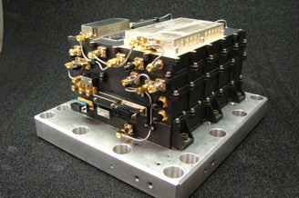
The Electra Unit is 17 by 22 by 14 centimeters in size weighing 4.9 Kilograms enclosed in a gold plated magnesium chassis. Thermal control is provided by heat rejection through the base installation plate of the unit.
As a Mars Orbiter passes within the field of view of a lander or rover, the two Electra units on the two vehicles establish a communications link. Based on the geometry of any given pass, the spacecraft Electra unit monitors the signal strength of the ground-based terminal to command it to different data rates during the pass based on the distance between the two. Data rates can be as low as 1kb/s and as high as 2,048kb/s in favorable conditions. Data that is received by the Electra system is then stored aboard the orbiter for downlink to the ground using its high-gain X-Band system.
This enables rovers to downlink large data volumes including science data, images and vehicle telemetry that could not be downlinked via their own communication system that can only achieve a fraction of the orbiter’s direct to Earth communications data rate.
TGO is extremely suitable for rover data relay given its low orbit, favorable for high data-rate communications via UHF.