
ERG Satellite Overview
Exploration of Energization and Radiation in Geospace
ERG – Exploration of energization and Radiation in Geospace – is a small satellite mission of the Japan Aerospace Exploration Agency to explore Near Earth Space – more precisely the high-energy particles inhabiting a vast area around Earth and the processes that drive particle acceleration for a better understanding of space weather dynamics which can have an effect on satellites and crews in orbit.
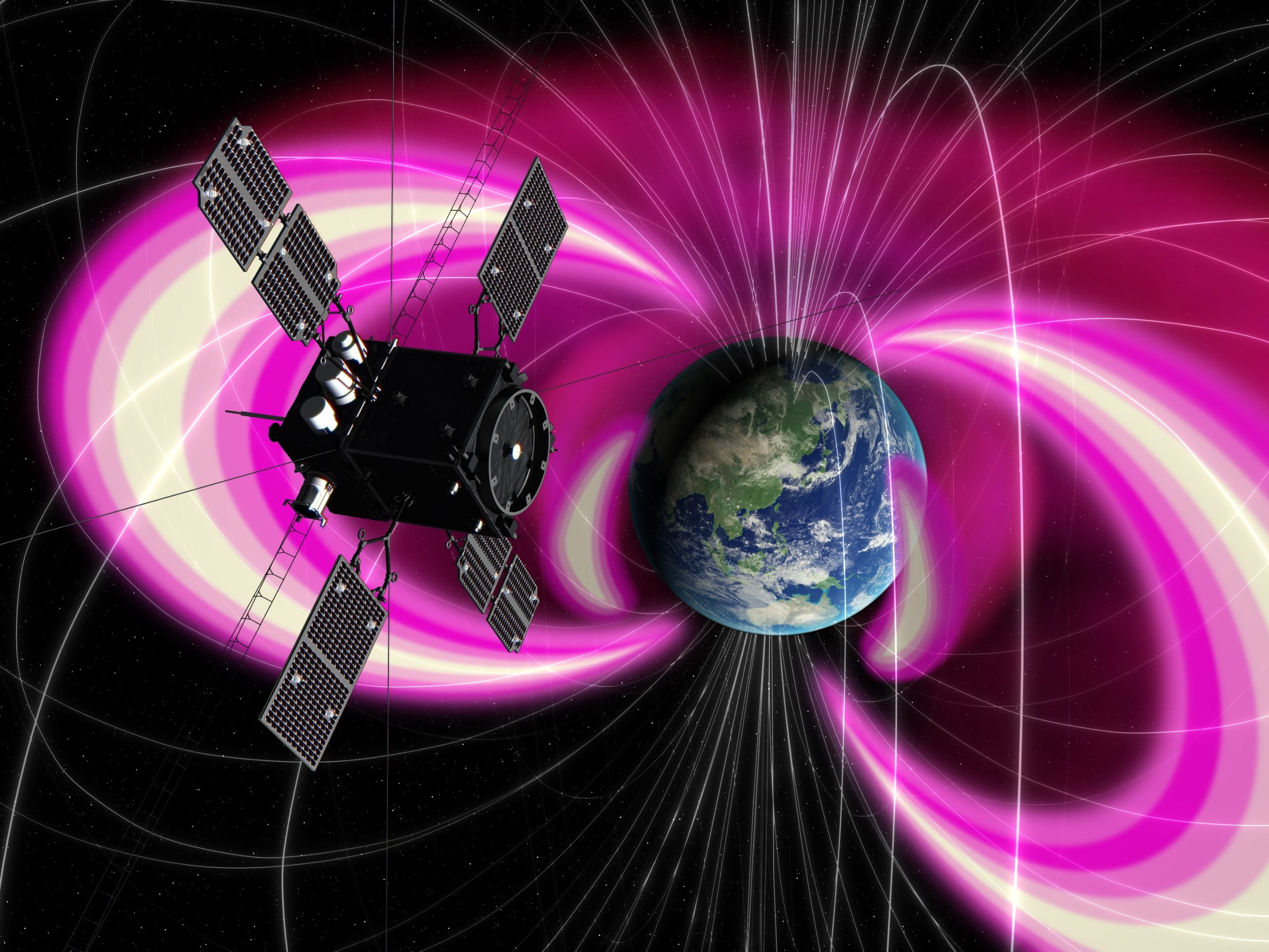
Geospace, the region of outer space near Earth, is home to a large population of high-energy electrons, protons and ions trapped in the Van Allen radiation belts created by Earth’s powerful magnetic field. Energetic particles are responsible for radiation-related upsets of electronics on satellites, harmful radiation to astronauts, and undesirable surface charging of orbiting spacecraft.
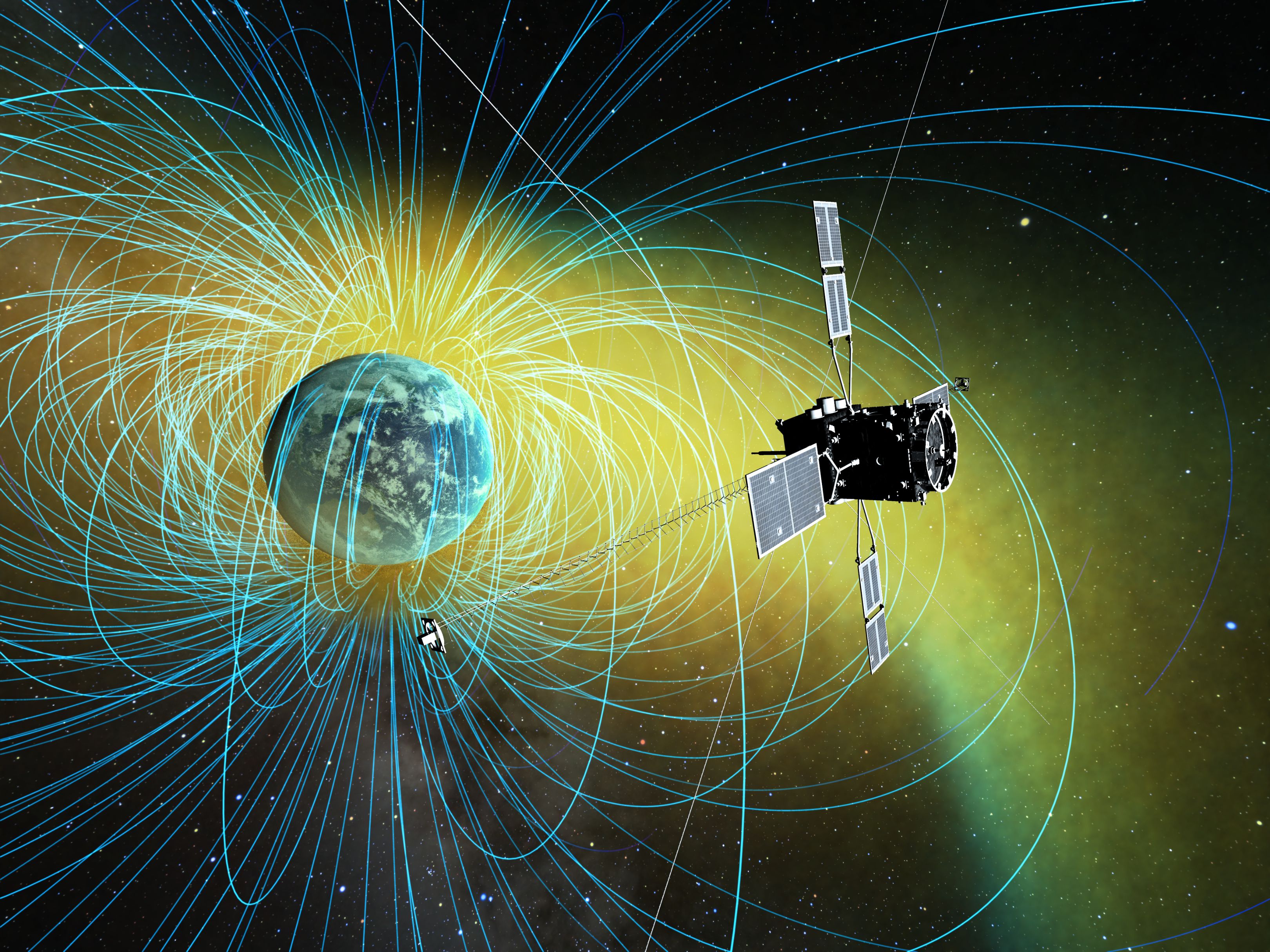
Earth’s radiation belts are highly dynamic regions of particle acceleration and energy transfer, typically exhibiting a structure of two belts, in inner and outer belt, plus – as recently discovered by NASA’s Van Allen Probes, a third belt that occurs during periods of active space weather events. A large population of electrons within the Van Allen Belts is subject to processes that cause them to form and vanish. ERG aims to reveal the mechanisms that drive the creation, acceleration and loss of high-energy electrons to help understand how space storms form.
The ERG spacecraft is outfitted with a suite of instruments to make detailed observations of electrons and ions near the equatorial plane – an area where electron acceleration is believed to take place. The instruments allow ERG to capture data across a wide energy range and for a variety of species to deliver a comprehensive picture of the particle population in near-Earth space and changes undergone due to external influences.

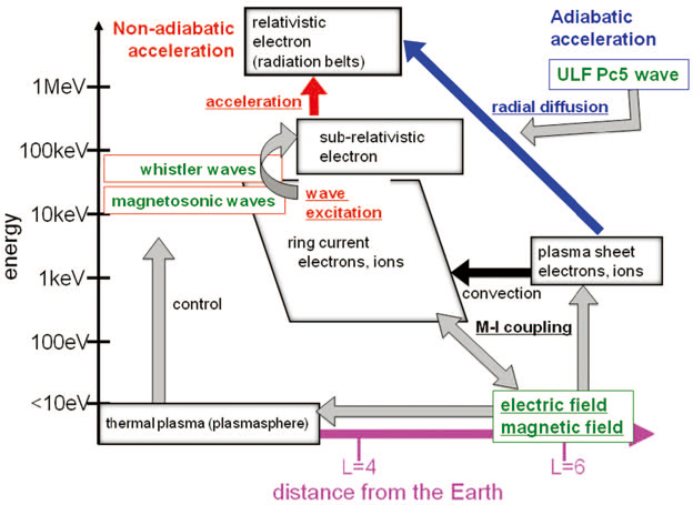
The mission’s primary focus is on relativistic (near the speed of light) electron acceleration in the context of the energy coupling of wave-particle interactions and the dynamics of space storms. For that, ERG takes a complete inventory of particles and fields in geospace – permitting an examination of the interplay between different plasma and particle populations of the inner magnetosphere, plasmasphere and radiation belts.
Two phenomena are of particular interest for ERG: Electromagnetic Ion Cyclotron (EMIC) waves and Whistler Mode Chorus.
EMIC waves are longitudinal oscillations of charged particles in Earth’s plasma environment, propagating roughly perpendicular to the planetary magnetic field. This process has been tied to the depletion of Ultra-Relativistic Electrons responsible for the third Van Allen Belt, leaving behind the narrow ring of particles protected inside the Plasmapause, thus keeping the narrow ring stable for extended periods of time.
Relativistic Electrons with less energy than the Ultra-Relativistic Electrons are depleted by Very Low Frequency Chorus that can cause particles to precipitate out of the belts into Earth’s atmosphere. Understanding which electrons are responsible for the creation of the chorus and which are accelerated by the chorus is one of the goals of ERG.
ERG attempts to make a direct measurement of the energy flow among waves and plasmas to further the current understanding of the cross-energy coupling driving highly-energetic space weather processes.
The ERG observatory is launched in the declining phase of Solar Cycle 24 with a mission life of at least one year, operating in an orbit peaking over 30,000 Kilometers above the equator, taking the spacecraft to a distance of five Earth-radii and into the L-shell of the outer radiation belt where the highest particle flux occurs. A slow decline from a peak altitude of 33,200 Kilometers down to around 30,000km will allow the satellite to sample areas where different processes are thought to be at work.
An orbital inclination of 31 degrees was selected so that the satellite will not always stay at the magnetic equator to make off-equatorial observations that are essential when attempting to understand the propagation of plasma waves from the equator into the radiation belts.
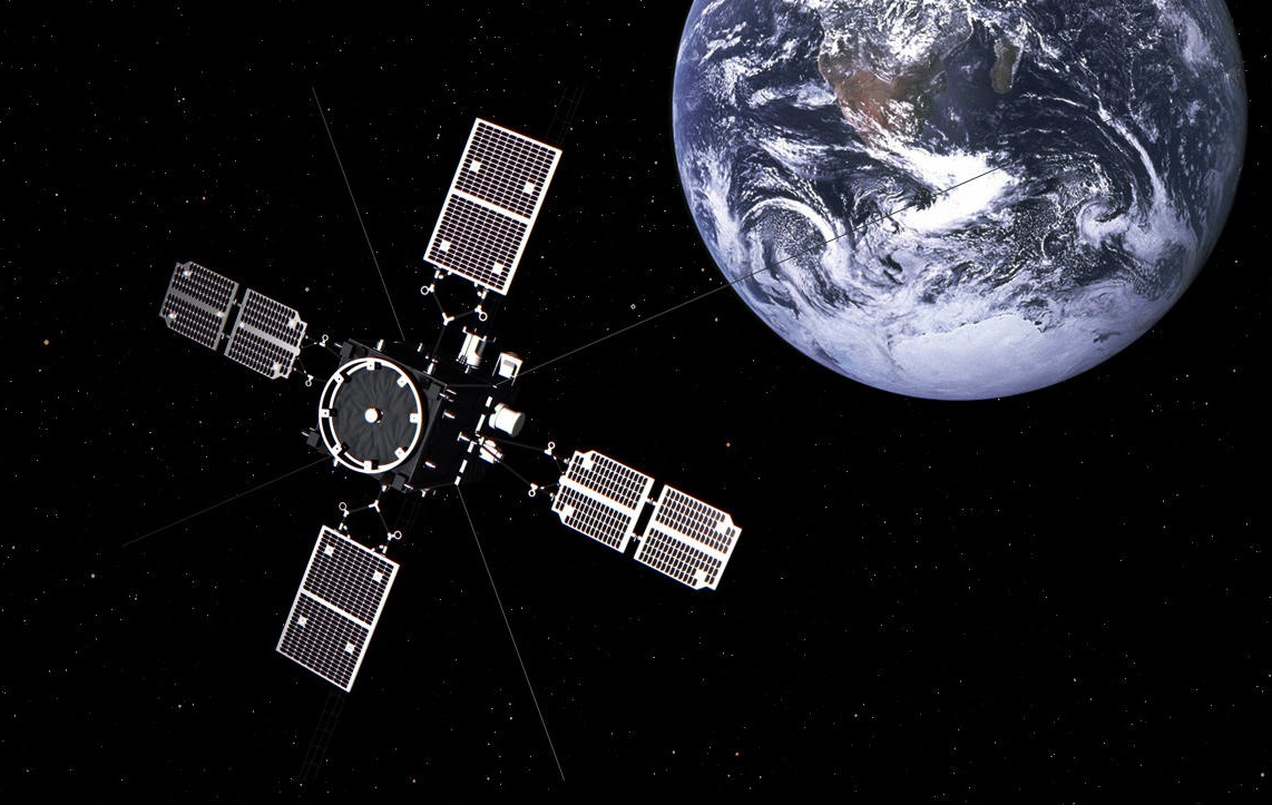
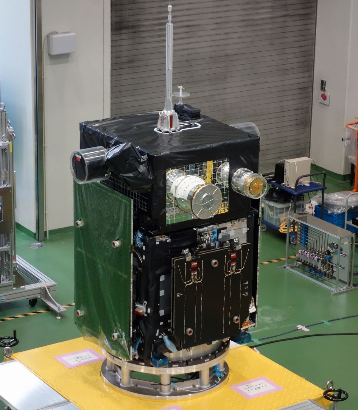
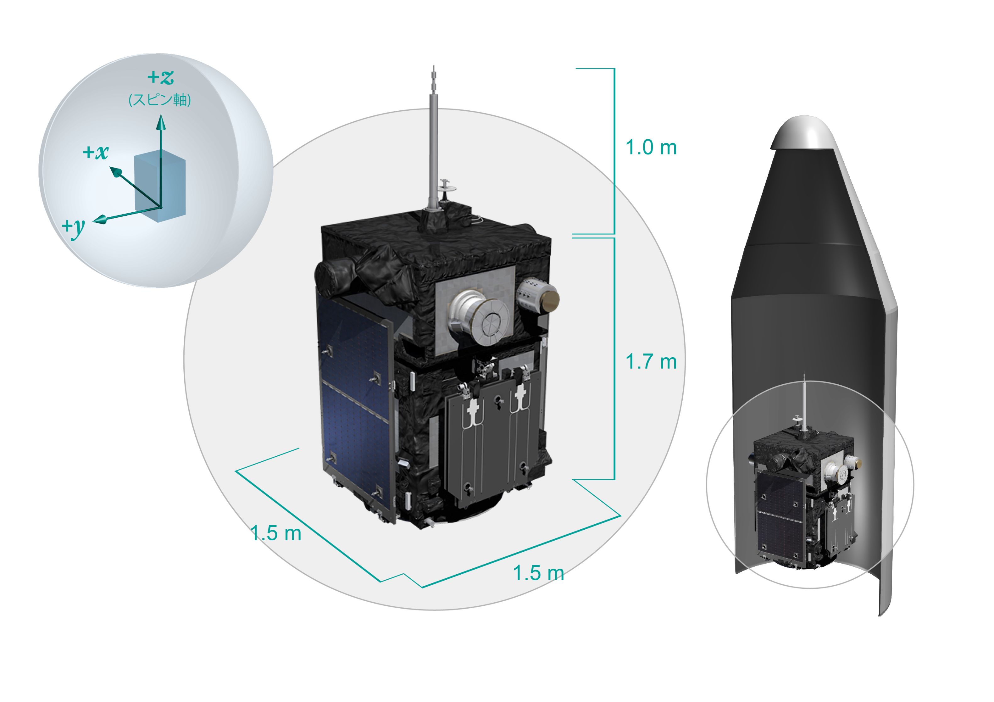
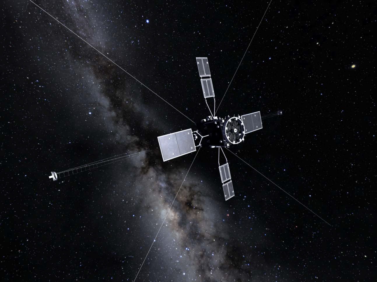
ERG is a small satellite mission, employing the SPRINT satellite bus that was first used on the Hisaki (SPRINT-A) mission and can be outfitted with different payloads to act as a multi-mission satellite bus. The ERG satellite has a mass of 365 Kilograms and measures around 1.5 by 1.5 by 2.7 meters in size in its launch configuration, comprised of a platform module sitting underneath a payload module which hosts the various sensors and appendages.
The satellite hosts four deployable solar arrays – two one-panel arrays spanning 5.2 meters from tip to tip and a pair of two-panel arrays spanning six meters, installed on opposite sides of the spacecraft. The arrays generate over 700 Watts of electrical power that is delivered to a dedicated Power Conditioning Unit which generates the satellite’s power bus for distribution to loads and also controls the state of charge of the satellite’s batteries.
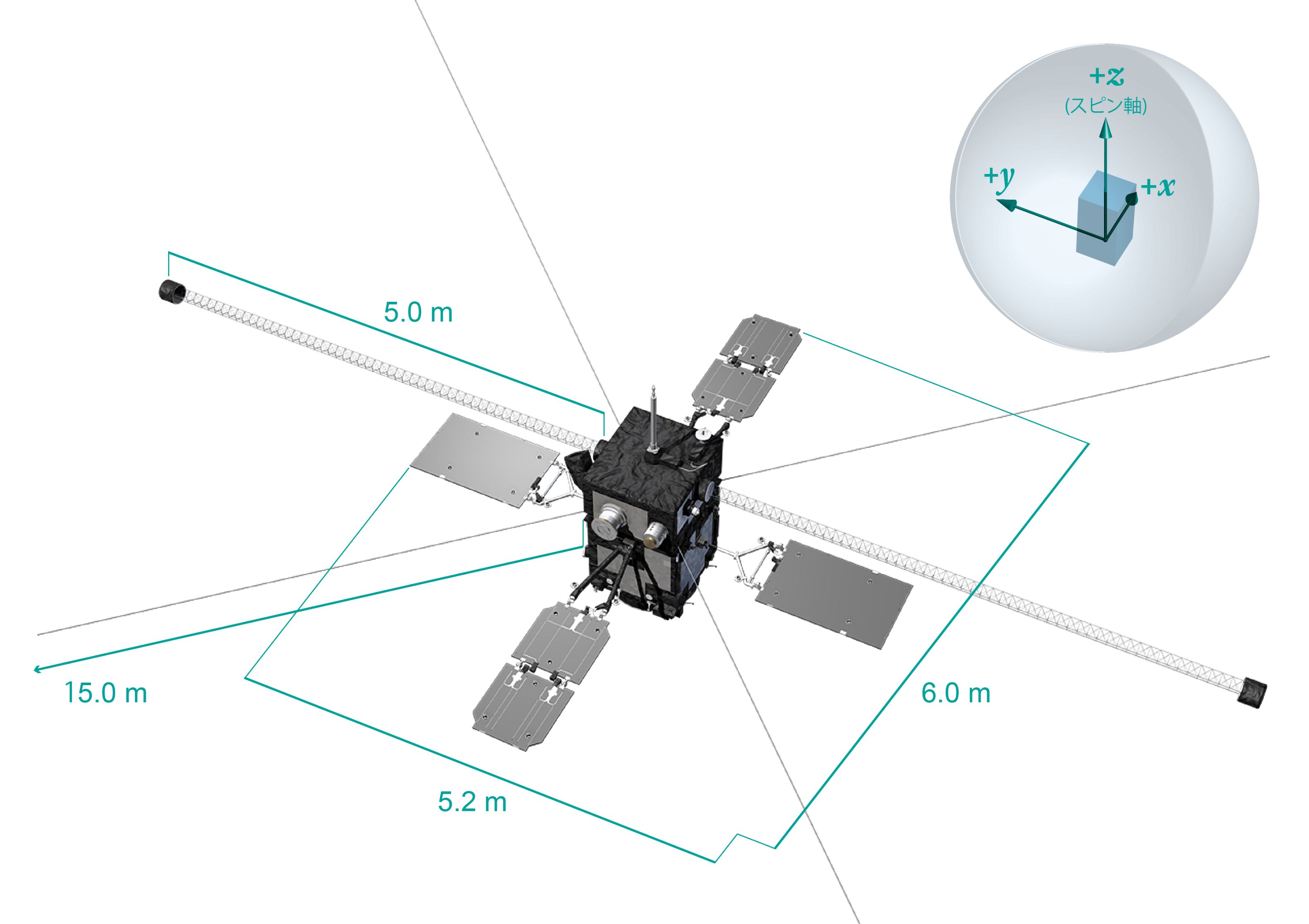
In addition to the solar arrays, the satellite hosts a series of other appendages for the scientific payload – a pair of five-meter long deployable booms on opposite sides of the satellite facilitate the magnetometer payload, and four wire booms, each 15 meters in length, extend from the spacecraft between the solar arrays to facilitate the particle and waves sensors.
Thermal control is accomplished with Multilayer Insulation and heaters to maintain acceptable temperatures during the cold portion of the satellite’s orbit with up to two hours spent in eclipse. Heat rejection uses silverized Teflon radiators installed on the X and Y-face panels of the observatory.
The ERG spacecraft employs spin-stabilization at a spin rate of one revolution every eight seconds (7.5 RPM) with the satellite typically pointed toward the sun for proper power generation. Spin stabilization allows the use of wire booms for the instrument payload, kept in a tensioned state by centrifugal force caused by the spacecraft rotation. A star tracker and Inertial Measurement System is used to deliver orientation data processed in an Extended Kalman Filter which generates a seven parameter angular-momentum-based state vector from which the spin axis and current orientation in space can be determined.
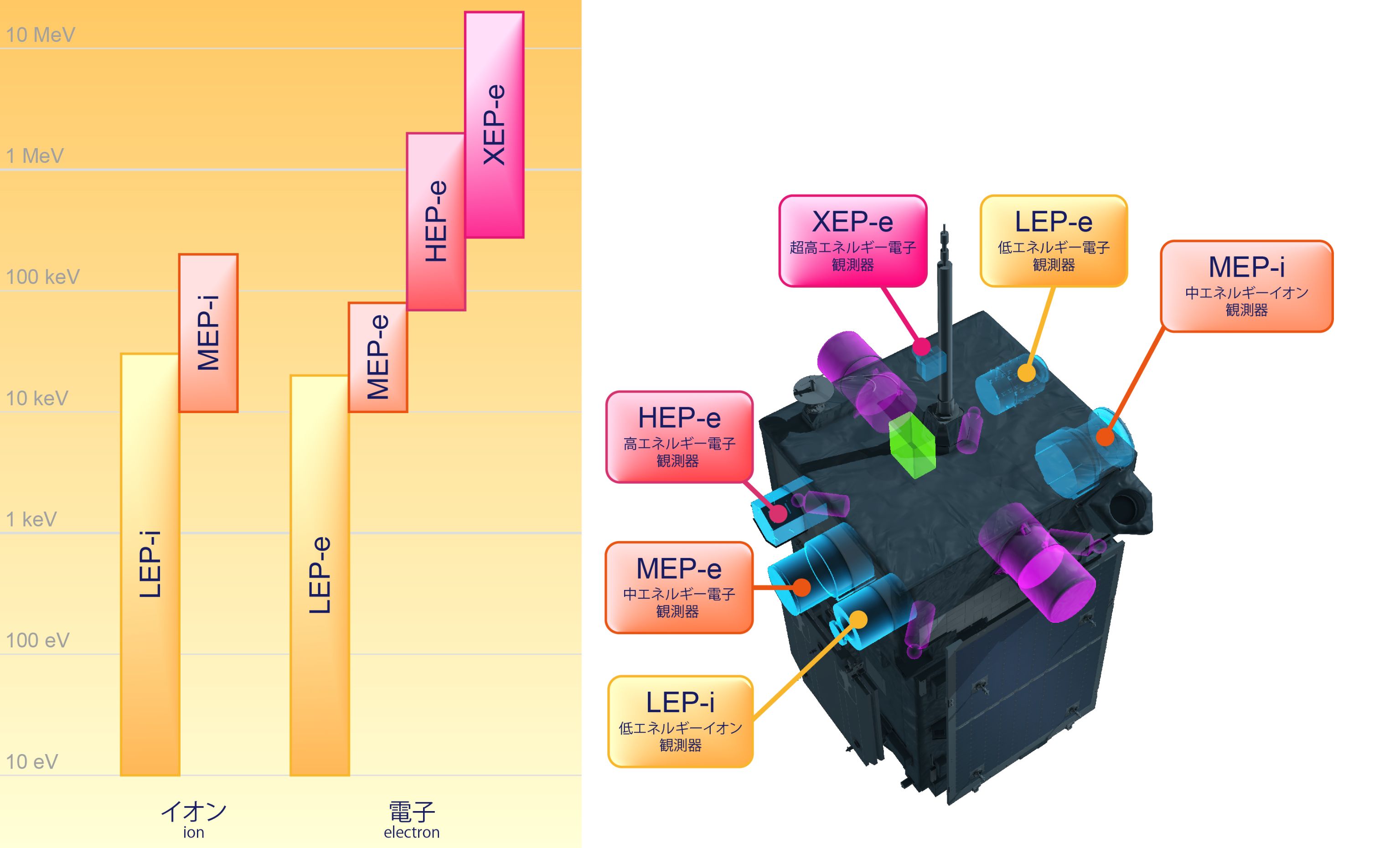
The ERG satellite hosts nine scientific instruments divided into three groups – A Plasma and Particle Experiment with six particle detectors, a Magnetic Field Experiment, and a Plasma Wave Experiment.
The Plasma and Particle Experiment (PPE) hosts four electron sensors (LEP-e, MEP-e, HEP, and XEP) and two ion sensors (LEP-i and MEP-i), covering an energy range of 10 Electronvolt to 20 Mega-Electronvolt for electrons and 10 to 180keV/q for ions.
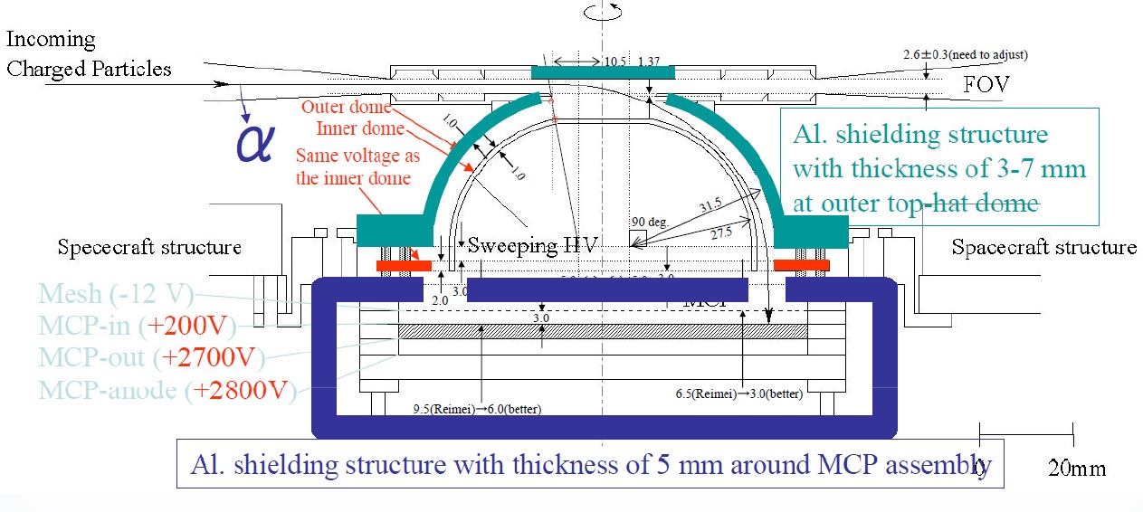
LEP-e (Low-Energy Particle Experiment – Electrons) covers the lowest energy electron population at 10 eV to 10keV with a 2.9 by 270-degree field of view. The sensor consists of a top-hat electrostatic analyzer, two deflectors and a Microchannel plate detector with an anode ring underneath. Two deflectors, one upper and one lower, change the path of electrons based on their energy before the electrons reach the electrostatic analyzer. The azimuth angle of impinging electrons is determined by measuring the position in which the electrons impact the detector with a position-sensitive anode while the elevation angle is measured perpendicular to the imaging plane to determine the direction of incoming electrons.
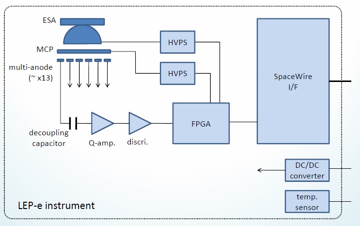
Azimuth of an incoming electron is is measured by determining which anode the electron hit. providing an accuracy of 22.5 degrees.
LEP-e is 20 centimeters in diameter and stands 30 centimeters tall, hosting an aluminum shielding structure 3-7 millimeters thick on the top hat and 5mm around the MCP detector assembly to shield them from incoming high-energy particles.
The MCPs are operated at voltages of 2700V by a dedicated High-Voltage Power Supply with a second power supply delivering a controllable voltage bias to the deflectors to set the energy of the electrons reaching the detectors. A Field Programmable Gate Array is in charge of commanding the power supplies and processes the analog instrument readout (after amplification) into digital data with 131kbit generated per spacecraft spin, transmitted to the spacecraft via SpaceWire.

MEP-e (Medium-Energy Particle Experiment – Electrons) hosts a Cusp-type electrostatic analyzer, similar in design to LEP-e, with a pair of deflectors that are operated at high voltage to select the electron energy. The electrostatic analyzer feeds a circular detector array with 5 x 5-millimeter silicon Avalanche Photo Detectors in which an avalanche of electron-hole pairs is generated when an electron strikes the detector. A measurement of the generated charge provides the deposited energy by the electron.
The detector assembly comprises 72 four-micrometer thick detectors to create an angular resolution of 5 degrees across a field of view of 5 x 360 degrees.
MEP-e, 30cm in diameter and 40cm tall, covers an energy range of 5-80keV at an energy resolution of 10% – energy is analyzed twice by MEP, first through the electrostatic analyzer via the deflector bias, and second using the charge read-out from the detectors.
Particles at higher energies can penetrate the MEP instrument housing and cause false detector readings, requiring a countermeasure for noise reduction, implemented as a coincidence detector making use of a Time-of-Flight method which rejects coincidental detector strikes. The development of detectors for electrons at tens of keV within the radiation belts has been a challenge due to the large population of high-energy particles which usually contaminates measurements by low-energy detectors.
LEP and MEP do not measure relativistic electrons that are of direct interest to the ERG mission, but represent important instruments that deliver a context measurement of the low-energy electron distribution function in the radiation belts to clarify how plasma waves are created.
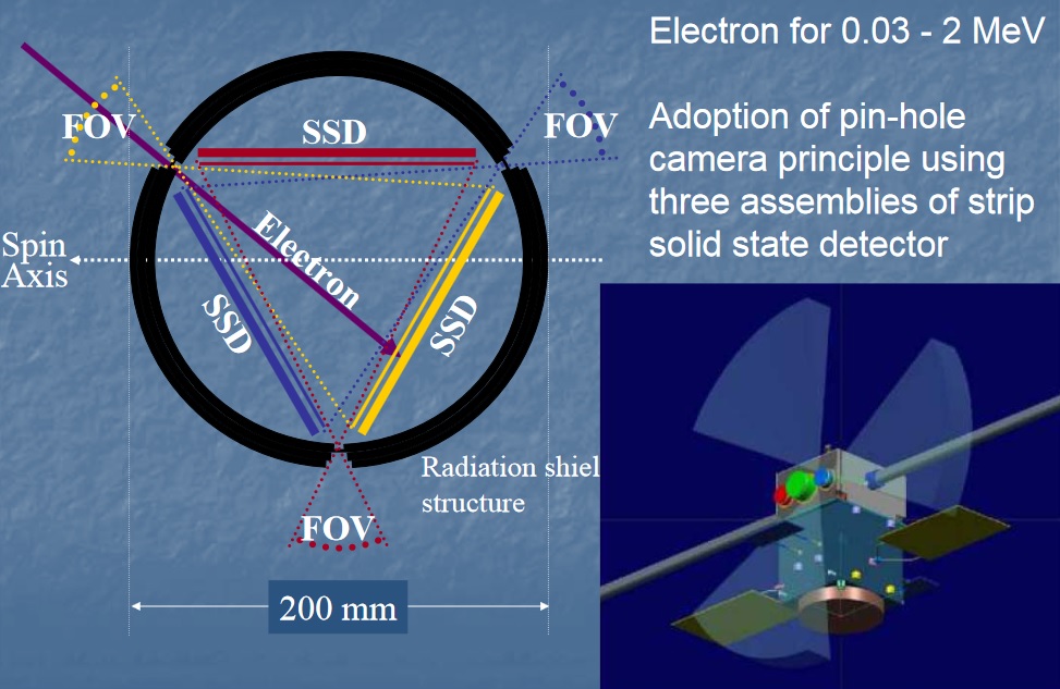
HEP-e (High-Energy Experiment – Electrons) comprises a pair of sensor heads – HEP-L covering electrons at an energy of 70keV to 1MeV and HEP-H that has an energy range of 700keV to 2MeV. The two sensors are similar in structure but have different geometry factors by a factor of nine. Each sensor comprises three identical assemblies, each with a 60 by 10-degree field of view to create a 180 x 10° FOV for the instrument, achieving an angular resolution of 10 x 10° for HEP-H and 5 x 10° for HEP-L.
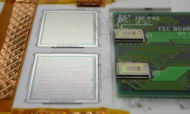
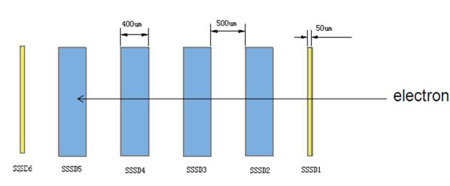
HEP employs Single-Sided Silicon Strip Detectors (SSSD) in order to achieve a sufficient energy and angular resolution. The SSSD consists of a bottom layer of Silicon semiconductor material in which electron & hole pairs are generated when high-energy electrons impact. The number of electrons/holes is proportional to the impinging electron’s energy and can be read out by measuring the charge arriving at the electrodes on either side of the detector. On the back side is a series of of aluminum strips to which the holes of the electron/hole pairs travel. Each Al strip is 200 micrometers wide with several micrometers in between and each strip has its own read-out electronics to provide position information. HEP’s detectors employ multiple layers of SSSDs.
HEP-L operates four 400-micrometer thick SSSDs with a gap of 500 μm to achieve the desired energy range as 90% of 1MeV electrons will be fully stopped after 1600 μm of silicon. In front of the stack sits another SSSD with a thickness of only 50 μm and an aluminum coating of 12 μm, designed to stop ions and reject protons.
Also, the thinner SSSD provides a more precise angular reading on the direction of the incoming electron and creates less electric noise for deposit energy detection. High-energy protons are rejected through a threshold analysis of energy deposited in the first two SSSD layers; A sixth SSSD sitting behind the stack detects all electrons that fully pass through the detector and can be disregarded as high-energy electrons.
HEP-L employs a 5mm aluminum shielding to reject particles that do not enter the instrument through the field of view. The entire HEP-L assembly is 5 x 4 x 1.8 centimeters in size.
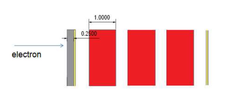
HEP-H uses thicker 1,000 μm (1mm) SSSDs because eight layers of the standard 400 μm detectors would be needed to cover the desired energy range, making the read-out electronics overly complex. As with HEP-L, a 50 μm SSSD resides in front of the detector for accurate position determination and ion/proton rejection, however, the aluminum layer is thicker at 250 μm. The 500 μm gap is retained from HEP-L and so is the use of a terminating SSSD to disregard electrons of higher energy that pass through all layers.
HEP-H also uses an aluminum shield and the assembly measures 12 x 8 x 2.6 centimeters in size. The entire HEP instrument weighs 3.0 Kilograms and is 20 centimeters in diameter and stands 20 centimeters tall.

XEP (Extremely High-Energy Experiment – Electrons) is responsible for measuring ultra-high-energy electrons at 400keV to 20MeV to gain information on the final state of energized electrons after undergoing acceleration processes. The instrument comprises a telescope with a 20-degree field of view feeding a Silicon Solid State Detector.
XEP employs a heavy shield of Aluminum and Tantalum metal to reject off-axis electrons, protons and ions, however, high-energy particles can still reach the detector – requiring an active anti-coincidence scintillator to identify particles that have to be disregarded. The scintillator surrounds the telescope and uses gadolinium silicon oxide that converts particle impact energy to photons which can be detected with standard photomultiplier detectors.
The XEP instrument weighs 4.5 Kilograms and is 19 centimeters in diameter and 25cm tall, achieving an energy resolution of 25keV.
LEP-i (Low-Energy Particle Experiment – Ion Mass Analyzer) is one of two ion detectors hosted by the ERG spacecraft, covering the lower energy range of 10eV to 25 keV/q. The instrument is a Top-Hat Electrostatic Analyzer coupled to a Time of Flight mass analyzer to identify ion energy and species.
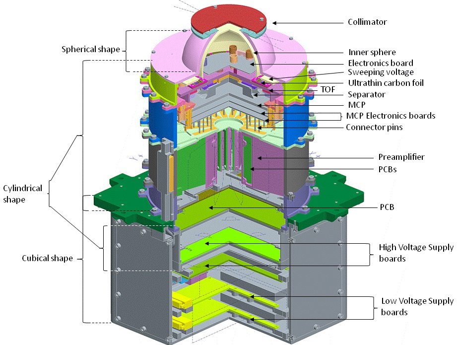
The LEP-i sensor head consist of an aperture opening, ion deflectors, start foils and anodes, a microchannel plate detector, stop anodes and foils, solid state detectors and pre-amplifiers as well as supporting electronics. It has a field of view of 5 by 290 degrees.
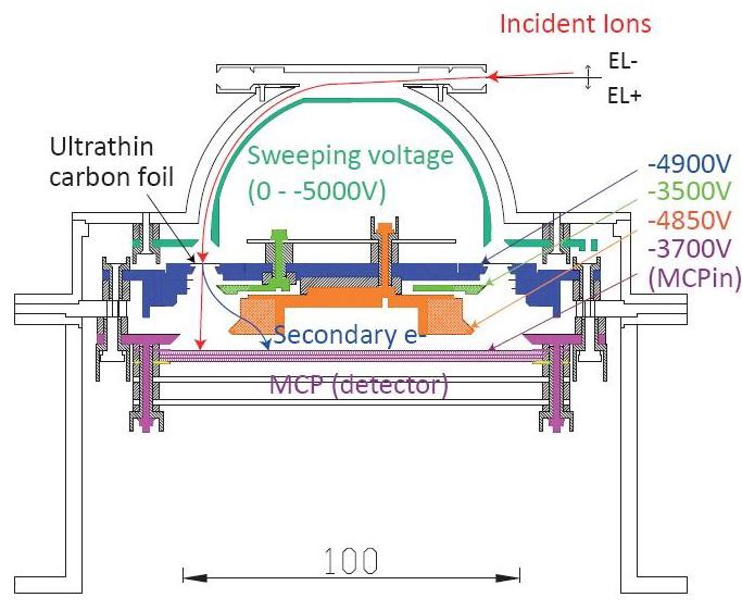
Incoming ions enter the two concentric toroids with the inner toroid having an adjustable voltage applied to match the energy of the entering ion. A particular voltage determines the energy and arrival angles of incoming ions and the instrument sweeps through a 0 to 5000 Voltage in a fixed period of time.
On the detector, an ion is detected on one of 15 anodes that are installed next to each other in a circular pie-type arrangement to provide ion elevation data with a sufficient resolution.
The ERG spacecraft rotation is used to sweep these 15 pixels through the three-dimensional sky to obtain a 3D measurement.
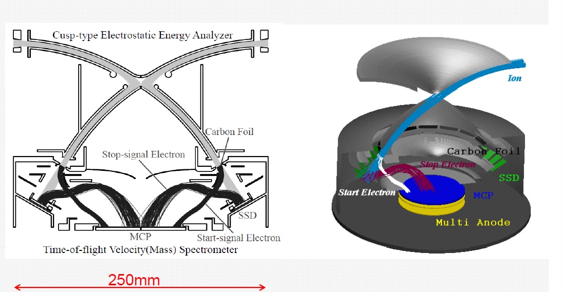
When entering the Time of Flight section of the instrument, ions are accelerated by a known potential and create secondary electrons when passing through an ultra-thin carbon foil – these electrons are accelerated to a specific energy in an applied electric field and are detected in a dedicated position on the Multichannel plate detector.
When the electrons are detected, a start signal is transmitted and when the ion arrives on the detector, a stop pulse is generated to determine Time of Flight of the individual ions. The time of flight, together with the energy measurement, can be used to determine the mass and with that the identity of the ion (through E=0.5m/v²). Ion flux is determined by counting the numbers of particular ions arriving per second.
Located directly under the MCP detector plate are pre-amplification electronics that deliver amplified signals to the instrument electronics where analog-to-digital conversion is completed. High-Voltage Power Supply boards generate the voltages needed for the various potentials in the detector including the sweeping deflector voltage. The Low Voltage Power Supplies reside at the bottom of an electronics box which itself resides directly under the sensor head.

MEP-i (Medium-Energy Particle Experiment – Ion Mass Analyzer) is responsible for the detection of ions at energies of 10keV/q to 180keV/q (mass range: q=1-32), using a Cusp-type electrostatic analyzer and Time-of-flight (TOF) mass analyzer, similar to LEP-i with a slight different in the path the ions take due to different deflector design. MEP-i has a field of view of 5 x 360 degrees and achieves an energy resolution of 15% and angular resolution of 5° x 22.5°.
LEP-i and MEP-i are capable of separating ions that are part of the solar wind such as hydrogen (H+) and helium (He++) from those that are present in the terrestrial plasma including hydrogen (H+), Helium (He+) and oxygen (O+). Knowing the source of the plasma will allow detailed insights into plasma flow rates into the diffusion region. When outside of the diffusion region, data from LEP/MEP-i can contribute to studies of geomagnetic storm dynamics.
The Magnetic Field Instrument (MGF) comprises a magnetometer sensor installed on one of the two deployable masts extended from the ERG spacecraft to remove the sensitive sensors sufficiently far from the satellite’s own magnetic field.
A measurement of the ambient magnetic, pulsations and electromagnetic waves is of critical importance for ERG to fulfill its mission objectives. Distortion of the ambient field created by ring current affects the particle distribution and trajectories in the magnetosphere and an accurate m-field measurement is necessary when attempting to understand the drivers of particle motion and acceleration.
The overall principle of the fluxgate sensors is identical – making use of the nonlinearity of magnetization properties for the high permeability of easily saturated ferromagnetic alloys to serve as an indicator for the local field strength. The ferromagnetic material is surrounded by two coils of wire – one coil runs an alternating electrical current which drives the core through an alternating cycle of magnetic saturation. This changing field induces a current in the second coil which can be measured by a detector.

In a magnetically neutral environment, the input and output currents would be identical, but the presence of an external field leads to an easier saturation of the core when in alignment with the core while saturation is less easily achieved when the core is exposed to an opposing field. This leads to the output current becoming out of step from the input which, with the known parameters of the core material and the simultaneous measurement of the input, will provide information on the local field strength using known calibration data.
The MGF instrument is designed to obtain the storm-driven deviation of the magnetic field from the intrinsic field with an accuracy better than 3 degrees. MGF supports two dynamic ranges: one narrow-range measurement of +/-8,000 nano-Tesla with a high resolution of 31 pico-Tesla and a wider range of +/-60,000nT with a lower resolution of 250pT. The instrument collects 256 readings per second, supporting measurements of very rapid phenomena such as the local ion cyclotron frequency which is an important measurement for the understanding of interactions between magnetic waves and the ambient plasma.

The MGF sensors on the outside of the booms are 4 x 4 x 8 centimeters in size and interface with an instrument electronics unit (15 x 16.5 x 5 cm) via an AWG#28 cable. The MGF booms are a lightweight truss structure that unfolds after the satellite is launched to a total length of 5.32 meters and a diameter of 27 centimeters. The entire MGF assembly has a mass of 4.3 Kilograms.
The Plasma Wave Experiment (PWE) comprises thirteen individual sensors installed on the ERG spacecraft platform, one of the two five-meter long booms, and four 15-meter long wire booms to measure electric and magnetic fields across a broad frequency range from a few milli-Hertz up to 1 MHz.
Many phenomena in Earth’s magnetosphere are generated as a consequence of wave-particle interaction, making an accurate measurement of waves and fields an absolute necessity when attempting to understand particle acceleration and loss. Wave-particle interactions are known to drive many kinds of plasma waves such as whistler mode chorus, plasmaspheric hiss, electromagnetic ion cyclotron waves and magnetosonic waves. Plasma waves are also hypothesized to be the drivers for both, electron loss and acceleration processes.
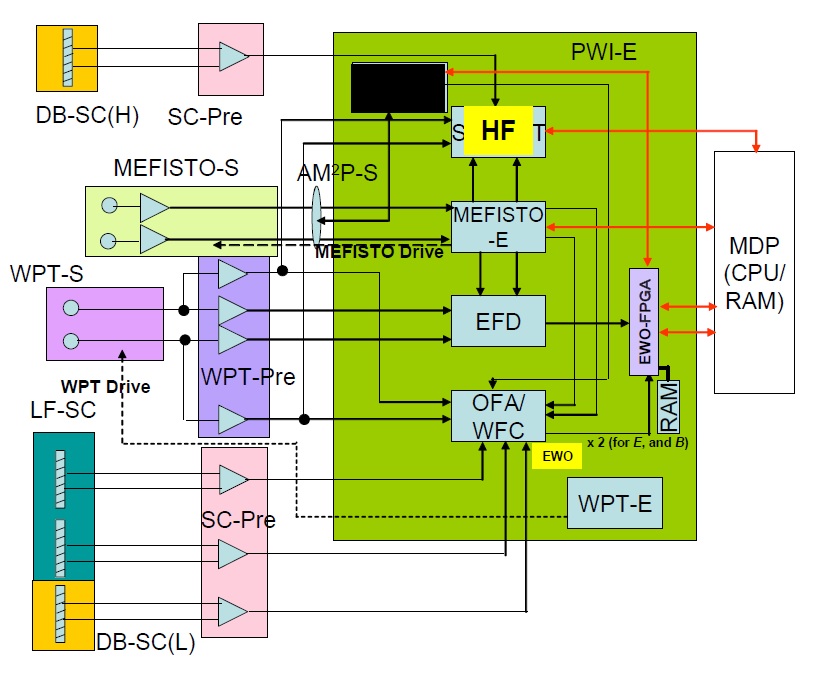
The electric field component is measured by two pairs of orthogonal dipole antennas with a tip-to-tip length of 32 meters provided by the extensible wire booms. Magnetic measurements are accomplished with a three-axial search coil on the satellite platform and one of the MAG booms. PWE is supported by an Electric Field Detector (EFD), Wave Form Capture (WFC), Onboard Frequency Analyzer and High-Frequency Analyzer which feed a pair of processing modules that generate the downlink data products for electric and magnetic fields.
The entire PWE instrument, including wire and rigid booms & electronics, has a mass of 10.3 Kilograms and draws 36 Watts of electrical power.
The Electric Field Sensors are facilitated on four wire booms extended in the spin plane of the satellite. Two opposing booms are dedicated to the Wire Probe Antenna (WPT) instrument, the other two make up the MEFISTO experiment (Mercury Electric Field In-Situ-Tool, Bepi-Colombo mission heritage).
The double probes measure the electric field in the spin plane by sensing the potential difference between the two current-biased metal ball electrodes installed at the end of the boom assemblies.
The thin 0.18-millimeter stainless steel wire booms of WPT have a length of 15 meters and interface with the boom deployment assembly mounted on the spacecraft deck and the upper segment of the boom that is deployed outboard. For WPT, the sensing element is a spherical probe, six centimeters in diameter weighing 50 grams. The MEFISTO experiment makes use of 0.1 to 0.3mm wires, also 15 meters in length and hosting titanium spheres, four centimeters in diameter.
WPT measures electric fields to a frequency of 10MHz and MEFISTO up to 3MHz, interfacing with the EFD and WFC receivers to capture electric field data as low frequency waveforms with 512 samples per second, wave spectra up to 20kHz and matrices.

Spectra below 200Hz and waveforms below 64Hz are continuously obtained for measurements of electromagnetic ion cyclotron waves. Electric and magnetic AC components in the medium-frequency range are stored as raw waveforms in the onboard memory of the satellite, but to comply with data downlink restrictions, onboard processing is employed to calculate wave spectra and special matrix through Fast Fourier Transformation. Raw waveforms at 60kHz sampling will only be downlinked after scientists identify events of interest in the low-resolution data.
The High-Frequency Analyzer collects wave spectra of the electric field at 10kHz to 10 MHz and magnetic field to 100kHz. A single probe installed on the ERG spacecraft is responsible for measuring the spacecraft potential at a 4Hz time resolution.
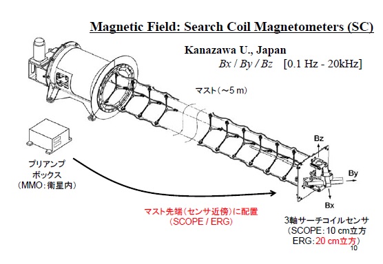
The Search Coil Magnetometer installed on one of the two 5-meter MAG booms measures the three components of the magnetic fluctuations from a few Hz to 20kHz which includes kinetic Alfvén waves, whistler mode waves and solitary waves. Data from SC will be used to determine the contribution of plasma waves to the turbulent dissipation that occurs in the diffusion region.
The SC instrument consists of three sensors that are mounted in a triaxial configuration to be able to measure magnetic field properties along all three axes. Each magnetic search coil consists of a fine wire wrapped around a 20-centimeter long ferromagnetic core. The primary winding collects the voltage induced by the time variation in the ambient magnetic flux. The three analog voltage signals from each sensor are routed to the amplification and processing electronics.

Processing of waveforms and spectra is completed in two CPUs, one for electric and the other for magnetic data with a unique synchronization technique used between them to enable cross-spectra analysis for the identification of events of interest which are processed as part of ‘PWE Bursts’ to deliver higher-resolution data. Two different burst modes are available – a Chorus Burst and an EMIC Burst (electromagnetic ion cyclotron waves).
A Chorus Burst contains several seconds of Very Low Frequency waveforms sampled at 65kHz while an EMIC burst contains several minutes of Extremely Low Frequency waveforms downsampled to 1024Hz. An automatic triggering system can also record significant plasma waveforms for other phenomena such as large-amplitude whistlers. Not all burst records can be downlinked to the ground, requiring scientists to prioritize individual events.
All raw waveforms obtained by PWE are delivered to the Software Wave-Particle Interaction Analyzer (S-WPIA) – a software-driven instrument designed to measure wave-particle interactions directly by calculating the correlation between waves and particles onboard the spacecraft.
Previous investigations of wave-particle interactions have used correlations of wave spectra and plasma energy spectra/velocity distributions that are observed by independent receivers and detectors. This method has the major disadvantage of different time resolutions in wave and particle data, making a quantitative analysis difficult.
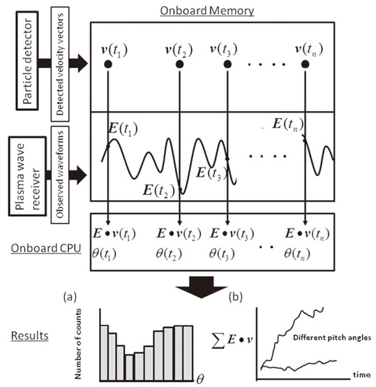
S-WPIA is connected to the spacecraft data recorder via SpaceWire and reads out all velocity vectors of particles caught by the detectors as well as the waveforms observed by the plasma wave instrumentation (PWE). The CPU reads out the stored data and calculates the phase between a velocity vector and the corresponding instantaneous amplitude – multiplying the instantaneous electric field vector with particle velocity to yield the time differential of plasma kinetic energy which corresponds to the quantitative energy flow among waves and plasmas.
Once the data is sorted according to phase, the distribution of the number of counts can be obtained as well as the time variability of particle acceleration which reveals the energy exchanged due to wave-particle interactions.
S-WPIA is capable of discriminating which electrons contribute to chorus generation and which electrons are accelerated by chorus waves – directly measuring how energy conversion takes place via wave-particle interactions in near-Earth space which had not been possible via a direct measurement before.