
Deep Space Climate Observatory
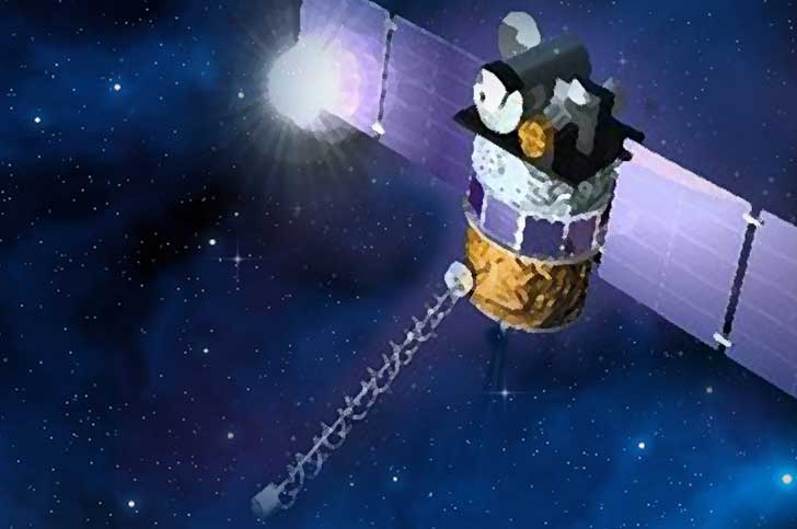
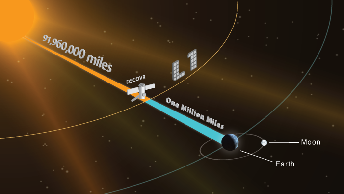
DSCOVR, formerly known as GoreSat and Triana, is the first operational spacecraft to be deployed to the Sun Earth Lagrange Point 1 to deliver continuous full-disk observations of Earth and measure space weather parameters, located in a position 1.5 Million Kilometers closer to the sun. The spacecraft carries a polychromatic imaging camera, an advanced radiometer and a plasma instrumentation suite to obtain measurements of the solar wind, the interplanetary magnetic field and observe the sun-lit portion of Earth.
Even before being launched, DSCOVR can look back at a storied history, being first proposed in 1998 by then Vice President Al Gore, naming the spacecraft after Rodrigo de Triana – the lookout who first spotted the New World on Columbus’ first expedition in 1492. Gore was inspired by the Blue Marble images returned by the Apollo missions and wanted to use regular images of the sun-lit Earth to raise awareness for environmental protection and a change in climate politics. From the L1 libration point, the sun-lit portion of Earth is continuously visible which is not the case from any Earth orbit.
Originally planned to launch aboard the Space Shuttle in 2002, Triana was baselined to be developed and manufactured on a 21-month schedule. In the spring of 2001, assembly of the spacecraft was nearly complete but the new Bush Administration de-manifested the mission from the Space Shuttle that was limited to six missions per year due to budgetary restrictions with priority given to missions to the International Space Station and the Hubble Space Telescope.
Having lost its launch date, the Triana spacecraft was placed in storage at the Goddard Spaceflight Center where it would remain for several years. In 2003, the dormant spacecraft was renamed DSCOVR – Deep Space Climate Observatory. The spacecraft was moved from storage in 2008 to undergo powered testing activities to assess the current status of the spacecraft as part of a feasibility study aiming to determine whether the spacecraft could still be flown after seven years of storage. Testing revealed that DSCOVR was in extremely good condition and NASA provided funding for the refurbishment and recalibration of the two Earth science instruments, but DSCOVR was still without a launch date and went back to storage.
Finally, in 2011, NASA, NOAA and the U.S. Air Force agreed to press on with the DSCOVR program using the existing spacecraft as a foundation, outlining advanced work to be done to prepare it for flight. This work included a conversion of the DSCOVR spacecraft from a pure Earth-monitoring craft to a Space Weather Mission with Earth observations taking the back seat. Work required on the spacecraft was the re-installation of star trackers, transponders, inertial measurement systems and reaction wheels that had been stored separately from the spacecraft. Additionally, ground support systems that in part were converted for other missions had to be readied for the resumption of the project. By 2012, the DSCOVR mission was secured with NOAA paying for the final refurbishment and launch preparation, and the Air Force procuring the launch vehicle.
Following assembly and detailed testing, DSCOVR was shipped to the launch site in November 2014 – reaching the final stretches of its long road to launch that took over 16 years.
DSCOVR delivers valuable space weather measurements from a unique location never been used before for an operational spacecraft, although data from DSCOVR will also serve a number of scientific purposes. The operational purpose of the mission is the collection of space weather data for the prediction of space weather events that could affect satellite operations, Earth-based radio communications and power grid stability.
Solar wind measurements from spacecraft at 1AU have been made over a period of decades, however, particle instrument limitations did not allow the observations of properties of the thermal solar wind particles in the kinetic regime which requires a measurement rate better than one reading per second. These measurements are critical in the understanding of the mechanisms behind the continuous heating of the solar winds as it propagates away from the sun.
This type of measurement will also provide information on how small scale magnetic reconnection operates in the solar wind when interacting with Earth, and how interplanetary shocks can accelerate solar wind particles to high energies.

Spacecraft Overview

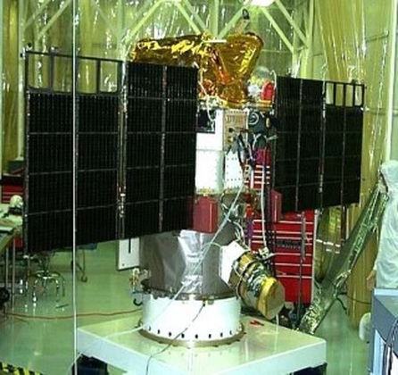
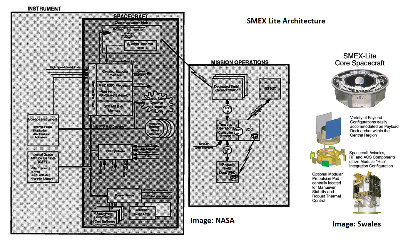
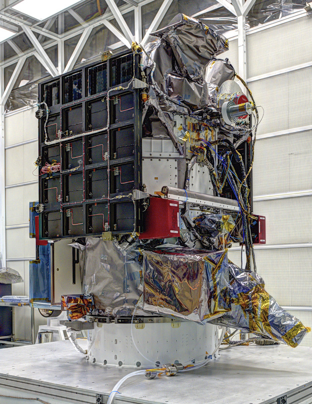
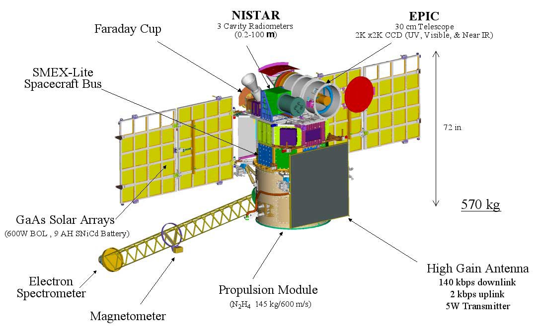
The DSCOVR spacecraft has a launch mass of 570 Kilograms measuring 1.37 by 1.87 meters in size with a dry mass of around 420 Kilograms. The spacecraft uses the SMEX-Lite platform supplied by Swales Aerospace, developed specifically for NASA’s Small Explorer spacecraft with a high degree of flexibility in mind to be able to facilitate a variety of payloads. The bus was used for five Small Explorer missions between 1992 and 2002. SMEX and SMEX-Lite were designed to support missions to Low Earth Orbit and high orbits using the maximum of radiation hardening to be able to tolerate a variety of radiation environments.
SMEX-Lite was developed out of the original SMEX satellite bus to create a more flexible and cost-effective design by introducing an overall plug-and-play architecture in which every major subsystem, all actuators and electronics are developed independent of the other systems to come together when all subsystem slices are integrated on a backbone system using standardized interfaces. This type of architecture also allows for an easy add-on capability of systems needed for particular mission needs as well as a simple capability of upgrades as new satellite technology becomes available.
The DSCOVR spacecraft is comprised of an octagonal bus module that resides between the cylindrical add-on propulsion section in the aft and the scientific payload in the forward section of the spacecraft.
The spacecraft bus has a mass of about 215 Kilograms, capable of supporting a payload of up to 400 Kilograms plus additional weight of the add-on propulsion module.
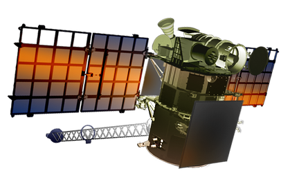
DSCOVR is equipped with two power-generating solar panels, each consisting of two segments.
The panels are rigid and do not have a sun tracking function since the spacecraft will usually point its Earth-facing panel toward the planet and the opposite side to the sun, ensuring proper power generation. The Gallium-arsenide solar cells deliver a total Beginning-Of-Life power of 600 Watts that is distributed to all spacecraft systems by using an unregulated 28-Volt power bus with dedicated avionics generating the power bus and controlling the state of charge of the battery module.
The sulphur-nickel-cadmium battery is comprised of nine cells with a total capacity of 9 Amp-hours which would allow the spacecraft to operate for over 20 hours in the event the solar arrays are pointed away from the sun which will only be the case for propulsive maneuvers, otherwise, the solar arrays will be in permanent sunlight.
Thermal control on DSCOVR uses a combination of passive and active systems. Multilayer insulation and protective coatings are used on a number of satellite components along with heaters that are operated based on readings from a number of temperature sensors installed on all satellite components. Radiators on the exterior of the spacecraft facing the non-lit side are used to dissipate excess heat from the electronics of the spacecraft.
The three-axis Attitude Determination and Control System of the DSCOVR spacecraft is comprised of sun sensors, an inertial measurement unit, a star tracker assembly, reaction wheels and a propulsive attitude control system using Hydrazine thrusters.
Six coarse sun sensors are installed on the different sides of the spacecraft to measure solar radiation intensity that will allow the Attitude Control System Controller to calculate the sun vector with sufficient accuracy to point the solar panels to the sun for optimal power generation. The sensors are used during initial attitude acquisition and in spacecraft safe mode.
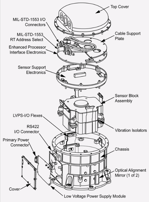
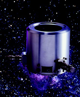
The inertial measurement system used by DSCOVR is Honeywell’s Miniature Inertial Measurement Unit. The Inertial Measurement Unit has extensive flight heritage and features a robust design using the GG1320 Ring Laser Gyro that provides precise rotation measurements. The system uses the basic principle that counter-propagating laser beams have different frequencies with the difference dependent on rotation rate which can be measured to calculate the rotation rate about the RLG’s sensitive axis. The MIMU weighs 4.5 Kilograms being 23 by 17 centimeters in size.
It has an operational measurement range of +/-375°/sec at a low bias of under 0.005°/hour. The system can tolerate the radiation conditions in Low Earth Orbit and handles accelerations of up to 25G.
DSCOVR has been designed for a Gyro-Less Safe Mode Attitude Control – not relying on any attitude information except for sun sensor readings and information from the reaction wheels. The safehold system uses wheel tachometers to estimate spacecraft body rates about the sun vector in order to achieve a sufficient accuracy in sun-pointing during safe mode periods.
The main source of attitude information for DSCOVR will be a CT633 star tracker and attitude sensor developed by Ball Aerospace. Optical imagery acquired by the star tracker is analyzed by an algorithm that searches a catalog of thousands of bright star constellations to be able to precisely calculate the three-axis orientation in space. CT633 combines all these functions into a single unit that completes all processing tasks of acquired imagery and delivers an attitude quarternion to the spacecraft computer that is then used in the attitude control algorithm. The stellar sensors provides a true lost in space function, being capable of re-acquiring the three-axis orientation of the spacecraft with no prior orientation information.
CT633 weighs about three Kilograms with a diameter of 13.5 centimeters and a length of 14.2 centimeters & an average power consumption of 8 Watts. It has a field of view of 20 by 20 degrees taking five images per second and being capable of stable tracking even at body rates up to 10 degrees per second. The star catalog contains 6000 stars, five of which are tracked simultaneously. Overall, the star tracker achieves an attitude accuracy of 6 arc seconds (cross-boresight) and 30 arc sec on roll about the imager boresight. From a total loss of spacecraft attitude, the star tracker requires under 60 seconds to acquire and identify stars.
Attitude actuation is provided by a system of four reaction wheels. The reaction wheel assembly is a rotating inertial mass that is driven by a brushless DC motor that spins the wheel. When accelerating the wheel, the satellite body to which the wheels are directly attached will rotate to the opposite direction as a result of the introduced counter torque.
Three wheels are needed for three-axis control, the fourth acting as a spare. Reaction wheel momentum dumps (de-spinning the wheels) are required every three months during the nominal mission for which the spacecraft uses its thrusters that counteract the force that results from de-spinning the wheels.
DSCOVR is equipped with ten thrusters that can be used for spacecraft attitude control as well as translational maneuvers that are required for mid-course corrections and orbital adjustment maneuvers around L1. Ten thrusters are fed from a pressurized Hydrazine tank, making use of the catalytic decomposition of hydrazine over a metallic catalyst bed to create a hot gas that generates thrust. With a total propellant mass of 145 Kilograms, the mission has a total delta-v budget of 600m/s which is sufficient for the transfer to L1, orbital adjustment maneuvers and regular reaction wheel momentum dumps.
Overall, DSCOVR can maintain its attitude with high-precision to keep any given location on Earth within a 25-Kilometer sector.
The central part of the Flight Control System of DSCOVR is based on a Power PC/6000 32-bit single board computer that offers radiation hardening to operate in the harsh space environment. The computer operates at a maximum clock rate of 33MHz and a processing speed of 10 MIPS (Million Instructions per Second). The CPU consists of 1.1 million transistors. It has an L1 cache memory of 8KB and controls up to 256MB of SRAM memory. The spacecraft control unit also includes 2.6GBit of mass memory plus non-volatile memory storing the flight software and command sequences without a loss of data in case of a power outage.
The various electronic cards and individual subsystem controllers are interconnected and connected to the flight computer via a backbone structure using high-speed PCI connections. The payload is connected to the data handling system by a serial RS-422 data link reaching a data rate of 1Mbit/s. The main command and telemetry bus of the satellite is a standard MIL-SRTD 1553 bus operating at lower data rates of 30kbit/s. All avionics installed on the spacecraft are radiation hardened and the controller is capable of operating all spacecraft functions autonomously without interaction with Earth for an extended period of up to several days.
DSCOVR is equipped with an S-Band communications system. A 5-Watt planar high-gain antenna 1.3 meters in height is installed on the Earth-facing panel of the spacecraft. This antenna is used for the downlink of instrument data at a speed of 140kbit/s. Telemetry from all spacecraft systems is transmitted via two omni-directional low-gain antennas installed on opposite sides of the spacecraft. These antennas are also used for spacecraft commanding, achieving data rates of 2kbit/s.
Instrument Overview
The DSCOVR spacecraft hosts three main instruments:
- A Plasma-Magnetometer Instrument Suite comprised of a fluxgate magnetometer, a Faraday Cup, an Electron spectrometer and a Pulse Height Analyzer
- NISTAR – The National Institute of Standards and Technology Advanced Radiometer
- EPIC – The Earth Polychromatic Imaging Camera
EPIC
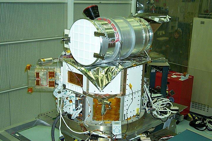
EPIC, the Earth Polychromatic Imaging Camera, is a 30-centimeter aperture telescope that gathers high-resolution images of Earth at different wavelengths to measure ozone, aerosols, cloud phase & height, hotspots on lands, and UV radiation on Earth’s surface.
The instrument was originally developed and managed by the Scripps Institution of Oceanography at the University of California, and Lockheed Martin’s Advanced Technology Center. EPIC can view the entire sunlit potion of Earth from sunrise to sunset at an almost constant scattering angle of 165 to 178 degrees.
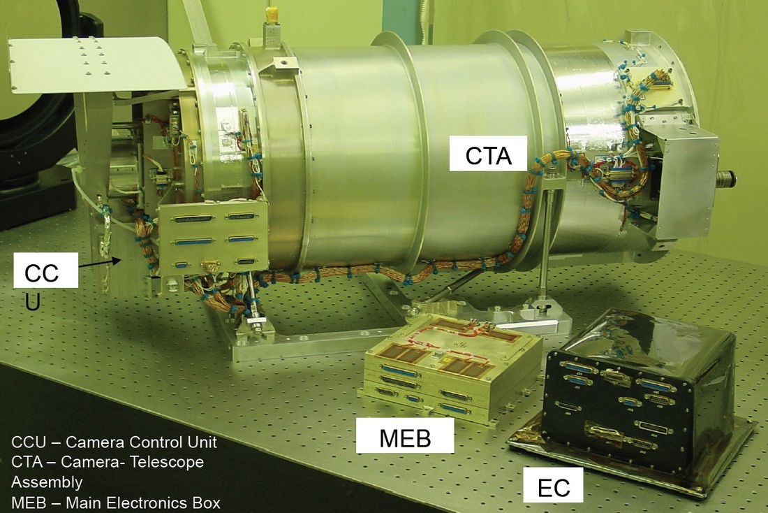
The instrument consists of three main components – the EPIC telescope, the Mechanisms Electronics Box and the EPIC Computer Box.
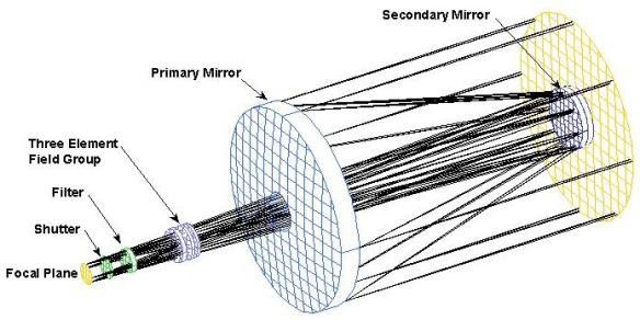
The telescope has an aperture of 30.5 centimeters using a Cassegrain type design consisting of two-mirrors placed on the optical axis of the telescope – a concave M1 primary mirror and an on-axis convex M2 mirror that focuses the light onto the Focal Plane Assembly, passing though a three-element field group, a filter assembly and a mechanical shutter. The optical system has a focal length of 282 centimeters. The M2 mirror can be adjusted by a mechanical system to achieve the best possible focus.
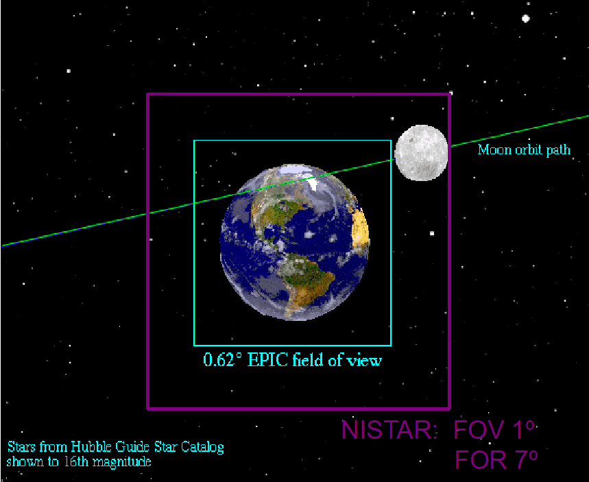
EPIC has a field of view of 0.61 degrees – at L1, Earth will have a width that varies between 0.45 to 0.53° meaning that the entire sun-lit portion of the Earth will be in within the frame at all times. The shutter system can support exposure times of 2, 10 and 40 milliseconds up to long exposures well over one minute. Multi-exposure imaging campaigns with 2ms-40ms timing and a 2ms resolution are also possible.
The Focal Plane Assembly hosts a Charged Coupled Device as detector that consists of 2048 by 2048 pixels with conventional pixel sizes of 15 by 15 μm. The detector uses a thinned backside illuminated design and is sensitive in a wavelength range of 200 to 950 nanometers, covering the UV, visible and near infrared spectral bands. The detector is cooled to –40 degrees Celsius using a passive cooling mechanism to reduce dark currents which are especially relevant for imaging in infrared wavelengths. Dark current will be on the order of five electrons per pixel and second.
The detector electronics support a readout rate of 500kHz. 2 by 2-pixel binning is employed, meaning that four active pixels are combined to one in order to increase the signal to noise ratio and correct for camera jitter that will be on the order of one pixel. Data is available as 1024 by 1024 raw bitmap and 12-bit JPG image format. In theory, EPIC achieves a ground resolution of 8 Kilometers per pixel, but due to optical distortion along the field of view, the actual resolution in the image center will be around ten Kilometers while the ground resolution on the edges will be 14 Kilometers. Most images will be downlinked after going through onboard processing that reduces data volume resulting in a reduction in ground resolution to 25 Kilometers.
Two filter wheels are part of the EPIC instrument to allow the instrument to cover ten different spectral channels (one open slot plus five filters per wheel). The wheels mechanically rotate to position a filter into the optical path covering ten channels from 317 to 779 nanometers. An overview of EPIC channels and associated data products is available in the following table:
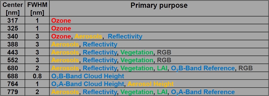
Data products delivered by EPIC include total ozone column, aerosol index, optical thickness and aerosol heights, cloud height, cloud fraction and surface albedo as well as vegetation index and land area index. “Real Color” images will be generated by combining the 388, 443 and 552-nanometer channels which will provide a reasonable representation of what Earth would look like to a human observer. Geolocation of images is done by using the edge of the sun-lit Earth and the outline of continents as reference. Stray light correction is accomplished through a data processing algorithm that uses pre-flight measurements of spread functions and an optical instrument model. Radiometric stability of the EPIC instrument will be assessed by regular analysis of ice-covered surfaces of Earth and dedicated imaging of the Moon’s sunlit face at a nearly constant phase angle when it is at its furthest distance from L1.
NISTAR
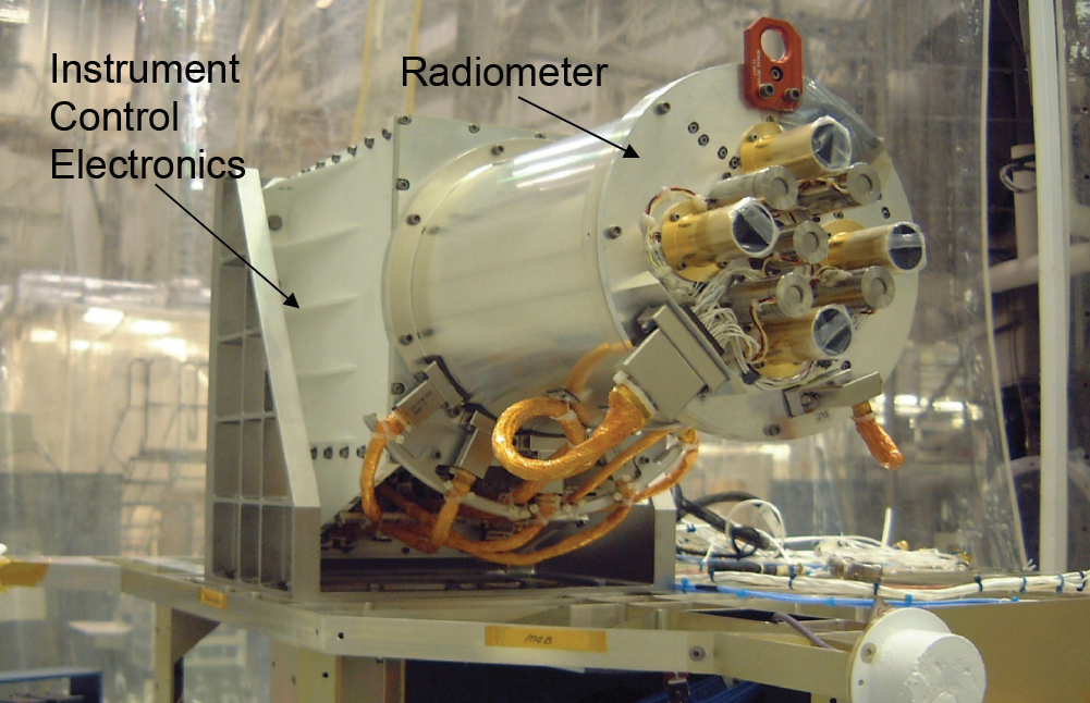
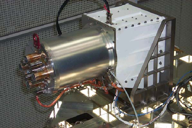
NISTAR is an advanced radiometer payload representing a joint development of NIST and Ball Aerospace. The instrument aims to measure the radiance output from the sun-lit Earth over a broad spectral range including UV/Visible wavelengths of reflected radiation, and infrared as an emitted radiation. The instrument determines the energy balance of Earth by measuring the input of radiation from the sun and the emitted radiation from Earth. High-cadence measurements over the entire planet offer unique insights into Earth’s energy cycle that otherwise would require a mission of several satellites in lower orbits.
Modeling of the energy emitted and reflected by Earth is difficult due to the uneven land, ocean and ice coverage and the ever changing cloud cover and vegetation. Measuring the radiances over a critical angle range is important in understanding Earth’s total radiant flux.
The NISTAR instrument consists of four separate detectors – three active-cavity electrical substitution radiometers and one silicon photodiode covering four different channels. The cavity radiometers consist of an instrument tube with a front window through which radiation enters the instrument and is directed onto an absorber. Internal heaters keep the cavities at constant temperatures, measured by sensors in the material and heater currents are recorded to determine the incident energy since the currents required to keep the elements at constant temperature drop with increased heat flux.
One channel covers a wavelength range of 0.2 µm to 100 µm stretching from UV to the far infrared to measure the total radiant power incident from the Earth-direction. A solar channel, 0.2 µm to 4 µm measures the reflected solar irradiance in the UV, Visible and Near Infrared range. A dedicated near infrared channel 0.7 µm to 4 µm measures the reflected solar radiation. The photodiode channel covers the visible into the near infrared wavelengths, 0.3 µm to 1.1 µm to act as a monitor of radiometer filter elements to serve calibration purposes.
Overall, NISTAR will be able to measure the Earth’s energy balance (solar input, Earth reflection, natural Earth emission) with an accuracy of 0.1% to improve the current understanding of the effects of changes in the energy balance caused by human activity and natural phenomena. NISTAR measurements represent the only measurements of the entire Earth’s reflected and emitted radiation at the retro reflection angle complementing data from orbital observatories.
The instrument has a field of view of one degree while Earth will have a size of around half a degree. The radiometer channels will complete one-minute long integrated measurements while the photodiode channel obtains measurements at a cadence of under one second to provide data on tracking stability of the filters, and co-alignment of the EPIC and NISTAR instruments. The photodiode channel is also in charge of observing the solar reflected broadband radiation from Earth with an extremely high temporal resolution.
NISTAR was calibrated against a portable version of NIST’s Spectral Irradiance and Radiance Responsivity Calibrations using Uniform Sources.
Plasma & Magnetometer Suite
DSCOVR hosts a suite of instruments dedicated to measuring solar energetic particles to provide an operational capability of monitoring incoming solar wind with sufficient lead time to provide warnings of potential effects of space weather events. Data gathered by the instrument suite will also be of great scientific value as no other spacecraft measured solar wind at a higher temporal resolution than DSCOVR.
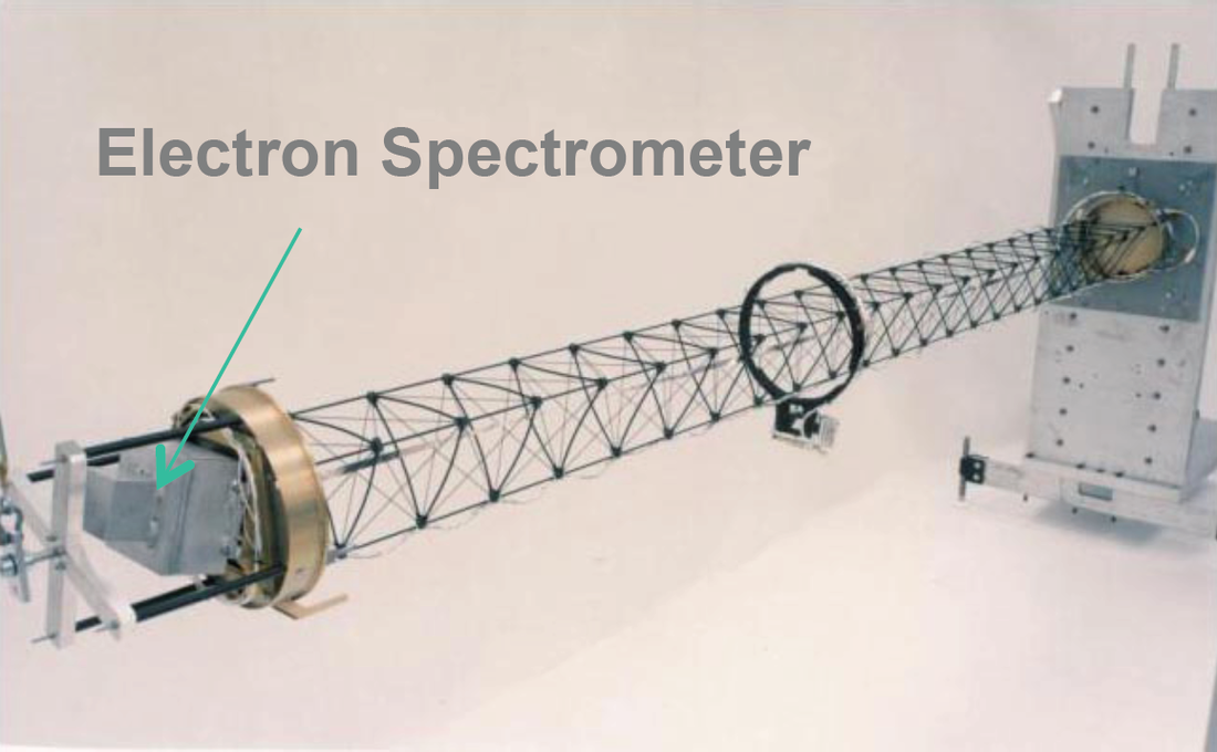
The Plasma and Magnetometer instrument suite consists of a fluxgate magnetometer, a Faraday Cup, and an Electron spectrometer. The instruments were developed at the Massachusetts Institute of Technology. The magnetometer and the electron spectrometer reside on a boom that is deployed from the main spacecraft body to move the magnetometer away from the spacecraft’s own magnetic field and avoid shielding effects on the electron sensor.
The magnetometer instrument is a triaxial-fluxgate magnetometer dedicated to measuring the three-dimensional magnetic field vector of the solar wind. The fluxgate sensors use the nonlinearity of magnetization properties for the high permeability of easily saturated ferromagnetic alloys to serve as an indicator for the local field strength. The ferromagnetic material is surrounded by two coils of wire – one coil runs an alternating electrical current which drives the core through an alternating cycle of magnetic saturation. This changing field induces a current in the second coil which can be measured by a detector.
In a magnetically neutral environment, the input and output currents would be identical, but the presence of an external field leads to an easier saturation of the core when in alignment with the core while saturation is less easily achieved when the core is exposed to an opposing field.
This leads to the output current becoming out of step from the input which, with the known parameters of the core material and the simultaneous measurement of the input, will provide information on the local field strength using known calibration data.
DSCOVR’s magnetometer has a sensitivity level of better than 0.1 nanotesla operating at a very high time resolution by making 50 measurements of the field vector per second.
The Faraday Cup measures the three-dimensional distribution of proton and alpha components in the solar wind plasma at a high repetition rate. It provides three-dimensional solar wind bulk properties at repetition rates of 0.5 to 2.5 seconds which can be coupled with magnetic field data to provide insight into solar wind waves and turbulence to learn about plasma properties and mechanisms of coronal heating. Multiple collectors are used to allow for the full range of solar wind deflections to be detected.
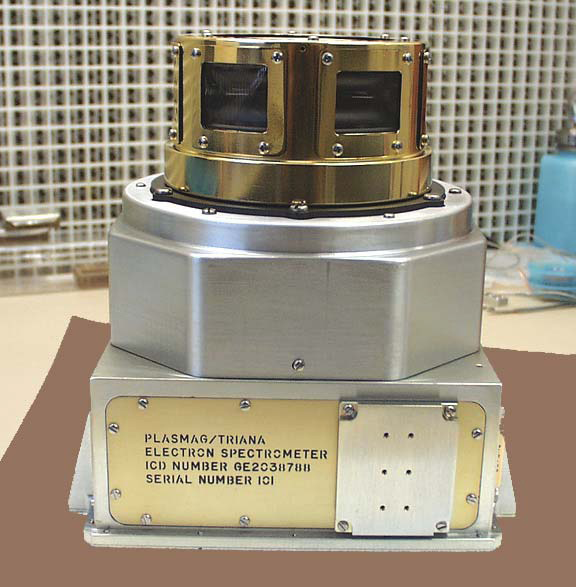
The electron sensor is a top-hat electrostatic analyzer measuring the electron energy distribution between 3 electronvolt and 2 kiloelectronvolt at measurement intervals of 800 milliseconds. The sensor consists of a top-hat electrostatic analyzer, two deflectors and a Multichannel plate detector with an anode ring underneath. Two deflectors, one upper and one lower, change the path of electrons based on their energy before the electrons reach the electrostatic analyzer. The azimuth angle of impinging electrons is determined by measuring the position in which the electrons impact the Multichannel Plate detector with a position-sensitive anode while the elevation angle is measured perpendicular to the imaging plane to determine the direction of incoming electrons.
Data from the electron sensor allows the continuous observation of the three-dimensional electron distribution function for various solar wind conditions thus providing the closest link to the formation of the solar wind on the sun’s upper corona.
Pulse Height Analyzer
Also part of the DSCOVR spacecraft is the Pulse Height Analyzer, a compact payload developed at the Goddard Spaceflight Center to study the effect of the space radiation environment on microelectronics by looking at Single Event Upsets. The experiment flew to space aboard the Shuttle on Mission STS-95 in 1998 and made measurements in the Low Earth Orbit environment where the Earth’s radiation belts still provide shielding from direct interaction with the solar wind. Deploying the system to L1 will deliver data on the behavior of electronics in the direct path of solar energetic particles.
The system hosts a High Linear Energy Transfer Radiation Spectrometer delivering in-flight measurement of a spectrum of ionizing particle energy, charge, and mass. These measurements can be used to generate a Linear Energy Transfer spectrum. Real time measurements provide insights into particle events that may lead to upsets on the DSCOVR spacecraft itself and potential effects on satellites in Earth orbit once the particles reach the planet.
Data Availability
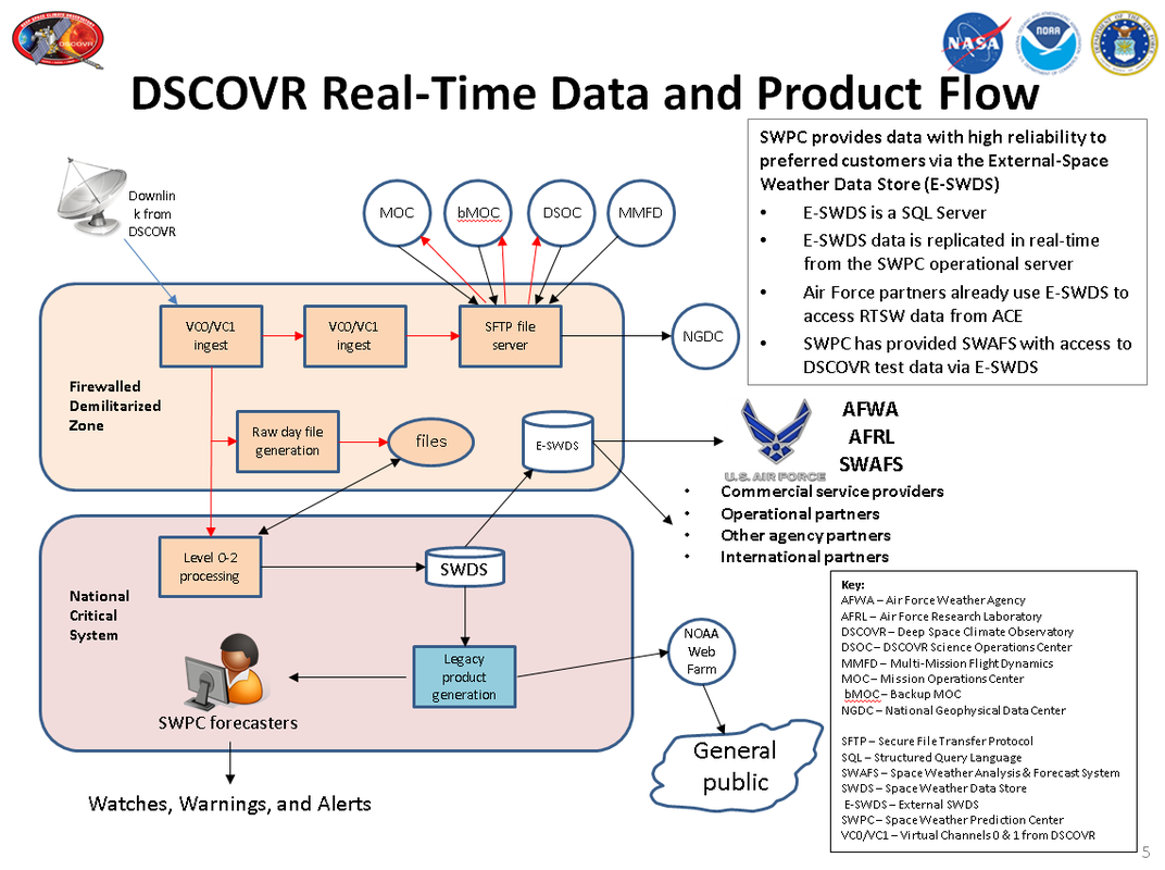
Data from the Plasma and Magnetometer instrument suite is downlinked to Earth in real time to support the operational task of the DSCOVR mission. The NOAA Space Weather Prediction Center will use real time data products for operational space weather monitoring and the generation of watches, warnings and alerts that are communicated to the general public via various channels including the NOAA website. A number of institutions will have access to raw data from DSCOVR in real time such as the National Geophysical Data Center. Level 1 and 2 data products are made available to commercial service providers, agency partners, international partners, operational partners and US Air Force branches via the External Space Weather Data Store. The General Public will have access to legacy DSCOVR data products via the NOAA web portal.
In charge of DSCOVR mission operations is the NOAA Ground Systems Division that is responsible for the end to end data flow to and from the satellite, uplink of command and housekeeping sequences, data storage, processing and distribution. Communications with the spacecraft are handled by NASA’s Near Earth Network with assistance provided by the Deep Space Network when needed.
Mission Profile & Orbit Design
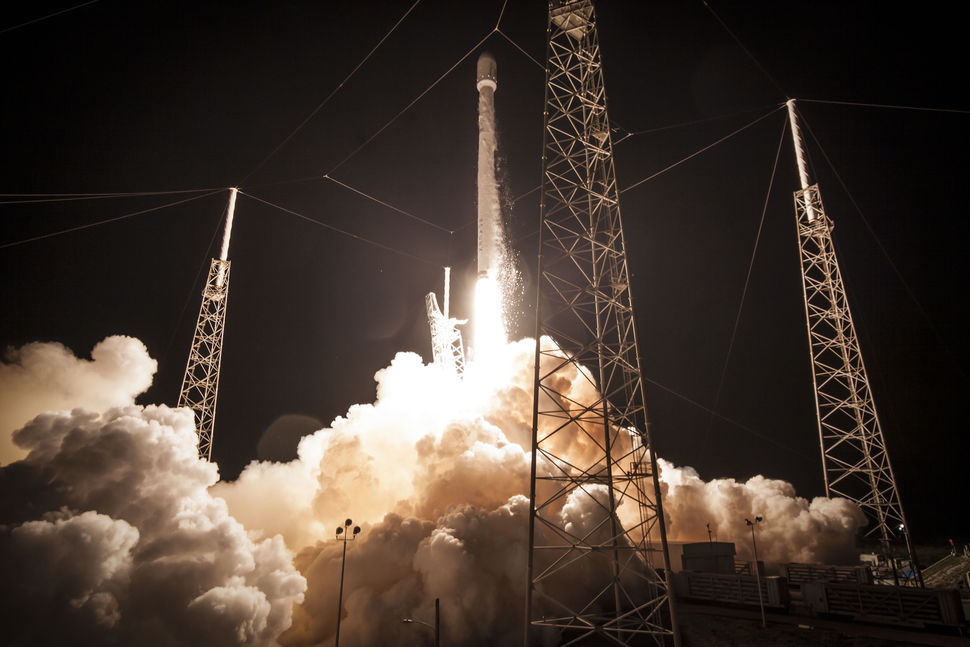
DSCOVR is launched by a SpaceX Falcon 9 v1.1 (F9R) rocket lifting off from Space Launch Complex 40 at Cape Canaveral Air Force Station in Florida. Lofting the light-weight DSCOVR into orbit enables the Falcon 9 to conduct a propulsive return attempt of the Falcon 9 first stage to a floating platform in the Atlantic Ocean, downrange from the launch site. The ascent path takes the vehicle to the north-east and the mission features two burns of the Falcon 9 upper stage, the first into a transfer orbit around Earth before the second burn injects the stack into an L1 Transfer Trajectory.
DSCOVR completes initial operations immediately after separation from the upper stage including the deployment of its two solar panels, the acquisition of a stable three-axis orientation and the initiation of communications with ground stations. The transfer to L1 has a nominal duration of 110 days which is typical for this type of mission profile since the excess approach velocity will have to be eliminated at the orbit injection around L1 at the expense of propellant.
Depending on launch vehicle performance, the DSCOVR spacecraft conducts its first Trajectory Correction Maneuver one day after launch once precise tracking revealed the trajectory of the spacecraft. Two additional TCMs are available during the cruise in order to set up the proper insertion conditions at L1. The L1 point is located 1.5 Million Kilometers from Earth on an imaginary line connecting the center of the sun and Earth.
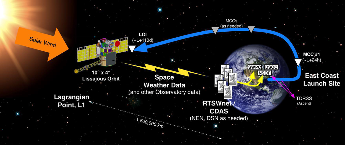
The L1 Lagrange Point offers a semi-stable gravitational environment that allows spacecraft to reside in orbits around the libration point over a period of years at the expense of few propellants for orbit maintenance.
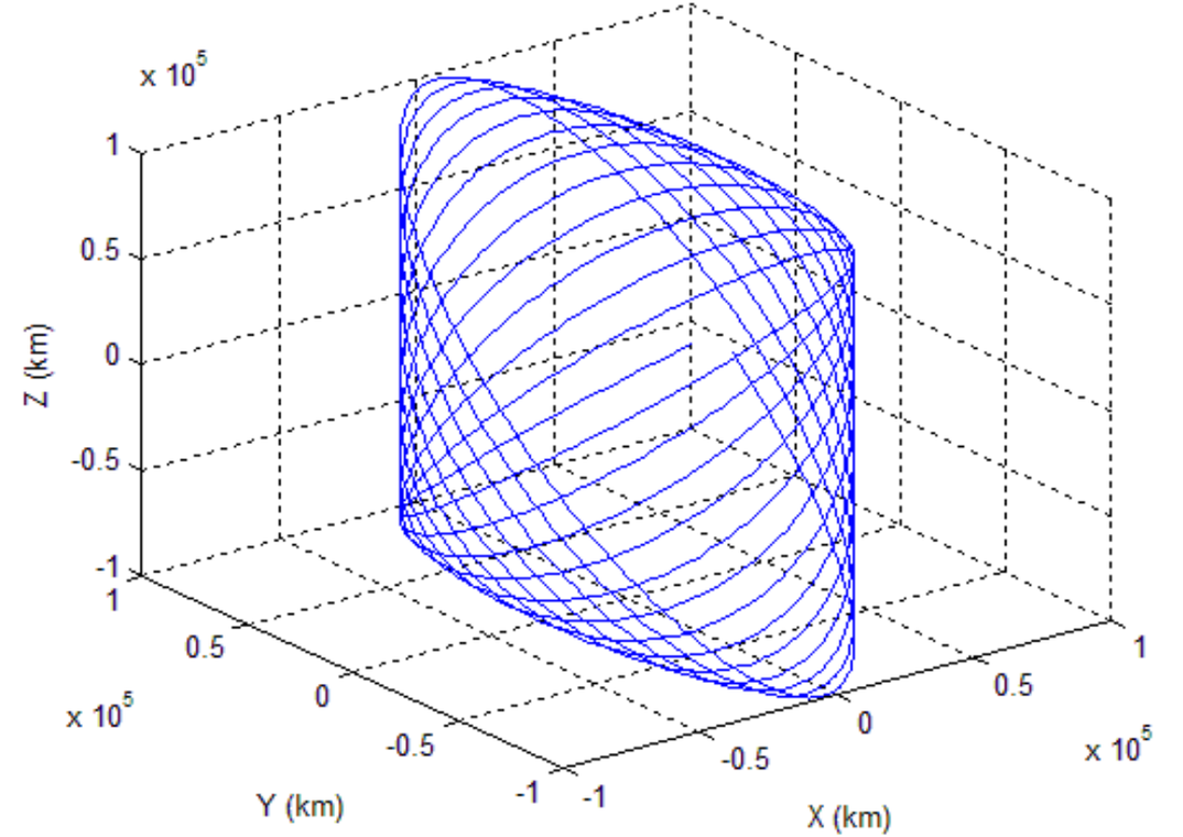
A Lissajous Orbit describes a Lissajous Curve around the Libration Point with components in the plane of the two primary bodies of the Lagrange System and a component perpendicular to it. Seen from Earth, DSCOVR will move within a 10 by 4-degree corridor once entering its target orbit.
In theory, Lissajous orbits are highly stable, but in practice, an orbit around a Libration Point is dynamically unstable – requiring some effort to model as small departures from equilibrium grow exponentially as time progresses. These departures require regular orbit maintenance maneuvers to preserve a stable orbit within mission parameters. The progression of a Lissajous Orbit is largely dependent on its initial parameters – namely phase angle and distance to the L1 point.