
OCSD-B & C CubeSat
The Optical Communications and Sensor Demonstration is a CubeSat technical demonstration mission by the Aerospace Corporation dedicated to testing of a small laser communications system that could increase the volume of data downlinked by small satellite missions. Furthermore, the satellite tests a cost-efficient optical sensing system for spacecraft rendezvous and stationkeeping.
The Aerospace Corporation was selected for the OCSD project by NASA in 2012 under the Small Spacecraft Technology Program. The goal of the project was the in-flight validation of a number of Commercial Off-the-Shelf components and subsystems, in particular communications and proximity operations capabilities.
The specific goals outlined by Aerospace Corp were the use of a laser for high-speed optical communications with a 30-centimeter ground station and the modification of commercially available products into a space-based navigation system for relative navigation in proximity to another satellite.
Three OCSD missions have been planned, the first acting as a technical demonstration of the various systems and testing the laser communications terminal while the next two satellites will be deployed as a pair to undergo rendezvous navigation exercises. OCSD-A, also known as AeroCube 7A was launched in 2015 as a secondary payload on an Atlas V rocket carrying the NROL-55 spacecraft and the two-satellite mission launches in 2017 aboard the Cygnus OA-8 cargo spacecraft supplying the International Space Station.
The development of high-capacity communications technology for small satellites has become one major factor over recent years as storage on CubeSats increased by orders of magnitude but communications systems did not see an improvement at a comparable rate. With today’s technology, a small CubeSat can readily hold one Tera Byte of data, though the most powerful communications systems operating in S- and X-Band will only reach data rates in the Mbit/s range which would make the downlink of several GB or up to a TB of data an extremely lengthy task, virtually taking years. To comply with the volume and mass limitations of small satellite missions, development in the field of communications shifted to optical communications technology that can reach the Gbit/s range even with low-power and low-mass space-based communications terminals. Though the major challenge was the miniaturization of laser communications terminals to fit into a CubeSat and still maintain their high data rates.
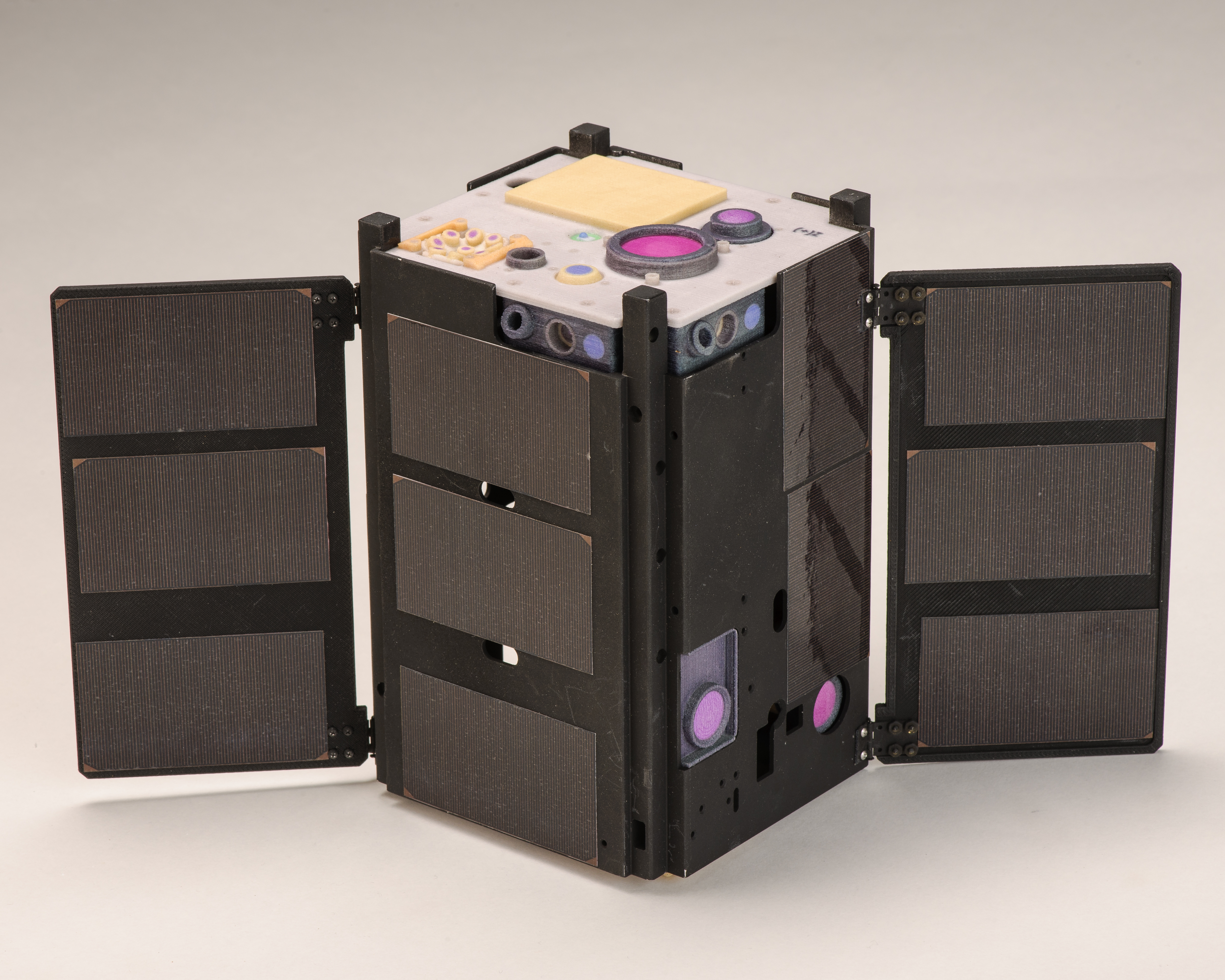
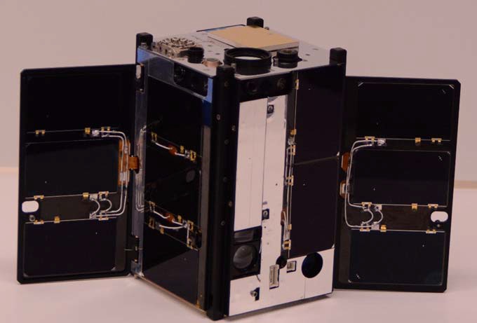
OCSD has a mass of around 3 Kilograms and follows the 1.5U CubeSat factor, measuring 10 by 10 by 15 centimeters in size. The satellite is outfitted with two wings for use in orbit control and power generation.
The satellites generate power by using solar cells installed on all side panels of the satellite plus the two wings. The wing surfaces and two of the rectangular satellite side panels each host three 1-Watt triple-junction solar cells while the two remaining side panels facilitate two 1W cells. The average power input from the solar cells is 4.5W with peaks at 9.5W. Power is stored in two high-energy Li-Ion batteries with a capacity of 14 Watt-hours plus two high-current batteries that can deliver up to 50 Watts of power to the laser for its brief operations. All EPS components are modified COTS products.
The Attitude Determination and Control System of the OCSD satellites has to provide sufficient accuracy for a) pointing the satellite to the proper direction during laser communications sessions and slewing appropriately to keep the laser beam centered on the ground station and b) pointing the satellite to the proper orientation for propulsive rendezvous maneuvers and relative navigation.
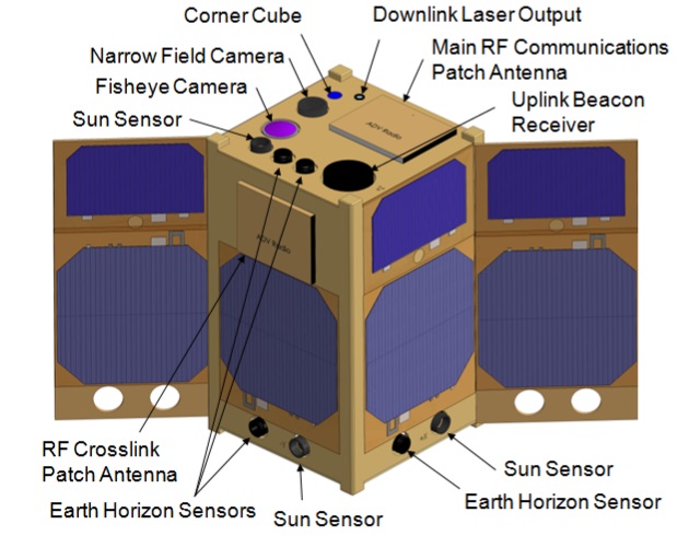
The Attitude Determination System hosts six two-axis 35° FOV sun sensors, four Earth-horizon sensors, a nadir Earth sensor operating on two-axes, and two sets of three-axis magnetometers. This sensor combination is well-proven as it has flown previous Aerospace Corp missions and can reach an accuracy better than one degree when properly calibrated. As an additional test objective, the OCSD satellites carry an infrared array sensor to locate Earth’s warm limb against the cold space background and help in determining the satellite attitude. The sensor array consists of 4 by 16 thermopiles, each capable of reading temperature differences of 0.25K over an operational range of -50 by +300°C. Each pixel has a 3.75 x 3.75° field of view, and in combination, the four sensors can reach an accuracy of 0.3° when all can see the Earth limb.
Furthermore, the satellites are outfitted with two miniature star trackers – one aligned with the +Z direction typically pointed zenith while the other is offset by 40 degrees to avoid interferences by stray light affecting both trackers. Two 3-axis gyro assemblies, one heritage component that has a higher power-draw but better bias stability than the other device that combines a three-axis gyro, three-axis accelerometer, a 3-axis magnetometer and a pressure sensor. The gyro data output is delivered to the ADCS controller where it is combined with the Star Tracker data to accurately determine the satellite attitude to within 0.1 degree.

In addition, a closed-loop control has been developed that uses a 10-Watt laser uplink sent from the ground station, co-aligned with the telescopic receiver and operating at a wavelength of 1,550nm. Four lensed photodiode receivers on the satellite are used to capture the uplink via an 18mm lens and 3mm Indium-Gallium-Arsenide photodiode. The individual currents measured by the different detectors is analyzed to calculate the two-axis pointing error and keep the downlink laser pointed at the ground station.
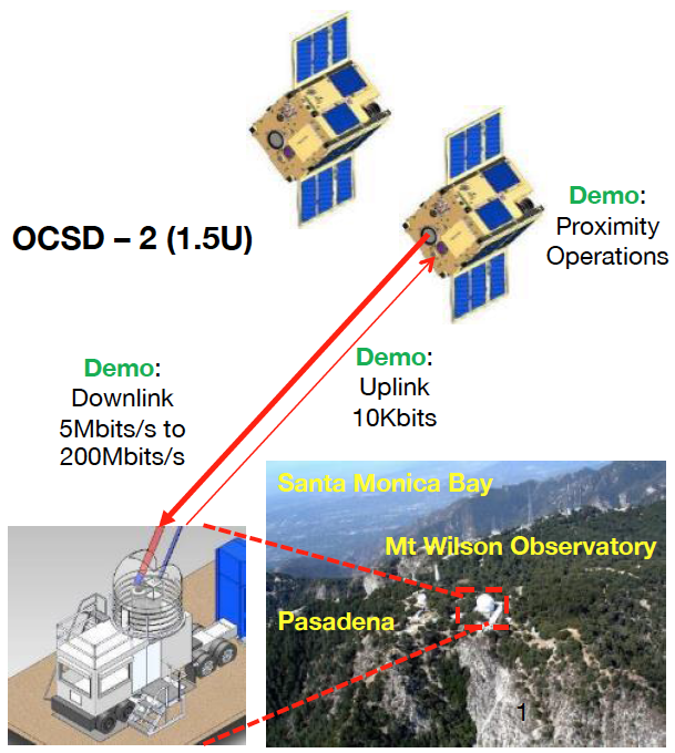
When operating in the closed loop system (with use of the magnetometers), the laser comm system can reach data rates of 50 Mbit/s. Operating the star trackers and gyros in open loop (without the ground uplink) can still permit communications at 50Mbit/s. Data rates are reduced to 5Mbit/s when the satellites only use the sun and Earth sensors, the magnetometer and the gyro system.
Attitude Actuation is provided by three reaction wheels and three magnetic torque rods. Both have previous flight heritage and can support an attitude actuation accuracy of 0.1 degrees and agile slew rates of up to 5 deg/sec.

The laser system used for the downlink of data features a 1,064-nanometer laser diode fed with 50 Watts of electrical power for an optical output between 10 and 12 Watts, depending on the temperature. Transmissions will be limited to three minutes due to power and thermal constraints as the remaining 40 Watts of power input are converted to heat energy, presenting a challenge to thermal systems on the satellites. The thermal energy is transferred through an aluminum mounting of the laser diode to the aluminum satellite structure that acts as a heat sink and long-term radiator.
The laser has a beam width of 0.35° which is the widest possible beam width for 50Mbit/s data transmission. A favorable link budget is available while the satellite is over 30 degrees in elevation as seen from the ground station.

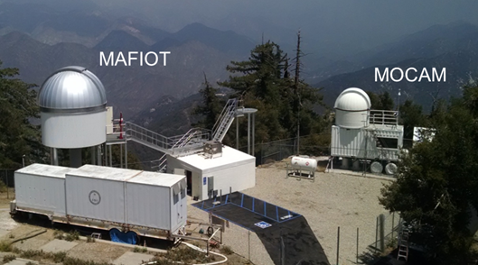
The OCSD project uses the Mobile Communications and Atmospheric Measurements Station at Mt. Wilson in California that is equipped with a 30-centimeter Meade receiving telescope. The receiver employs an avalanche photodetector coupled to avalanche quad photocells on the edges to provide error signals for the closed-loop tacking scheme. GPS data will be used to generate the basic tracking profile for each satellite pass and a tracking camera will be employed to keep the incoming laser beam centered on the photodiode.
The uplink for closed-loop tracking on the satellite side is located close to the telescope and has been approved by the Federal Aviation Administration. First experience with the satellite will be gained through the use of the uplink system before teams expect to purely rely on the satellite pointing itself to the correct attitude using data from the star trackers.

Another element tested by the OCSD satellites is a Water thruster propulsion system that has been manufactured from plastic using 3D printing. The water or ice is kept within an expandable volume to allow the water to expand and contract with temperature and change its phase as desired without touching the actual walls of the tank. For propulsion, the water is heated to 40°C to generate an inlet pressure of 6.9kPa as propellants are fed through a series of valves to a thruster nozzle machined from aluminum. Thrust levels can be varied from 3 to 5 millinewtons. The overall delta-v budget of each satellite is 10m/s, although only 3m/s are required for the planned proximity operations tests.
The thrusters and wings are used for the far-field rendezvous that aims to bring two OCSD satellites to within two Kilometers. The two wings can be extended and closed to actively modify the ballistic coefficient of the satellites by up to a factor of five for along-track phasing. Cross-track maneuvering will employ the thrusters.
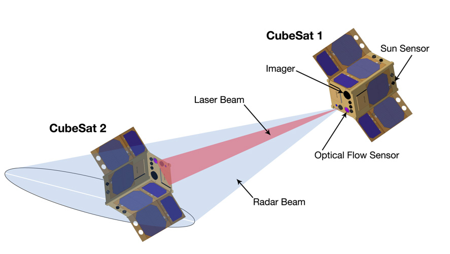
The OCSD satellites demonstrate a complex relative navigation system. GPS receivers are used to calculate precise orbital elements of the two satellites that are involved in the rendezvous. Orbital data is then propagated to generate pointing tables for upload to the satellites to allow them to roughly point their +X face to each other as a function of time specified in the pointing tables. The relative navigation system consists of a 670nm (red) LED and a color imaging camera. The target spacecraft will activate the LED while the chaser collects photos of the +X direction with a 38-degree field of view, 10-Mpixel color camera to capture the position of the LED that has an output of 0.3 Watts and a beam width of 60°. This system will be effective for ranges exceeding 200 meters to as far as several Kilometers. Additional LEDs are present on the +Z and -Z panels to recover from a Lost in Space Situation or in case of problems with the GPS pointing solution.
When an image of the target craft is collected, it is put through a Field-Programmable Gate Array for the precise calculation of the X and Y error angles between the two satellites with an accuracy of 0.016°.
When pointing has been established, the satellite that is actively pursuing the target will activate its Jenoptik laser range finder to measure the inter-satellite range with an accuracy better than one meter using a pulsed 1550nm laser source. The range finder can be used from a distance of up to 5 Kilometers, provided the pointing error is under 0.2°.
The first OCSD satellite launching with NROL-55 will test out all the satellite subsystems with particular focus on the various attitude sensors and actuators as well as the thruster system and laser communications architecture. Two Block-II satellites that include changes based on lessons-learned with the pathfinder will be launched in the coming years to conduct the actual in-orbit rendezvous mission.
