
ISARA Satellite
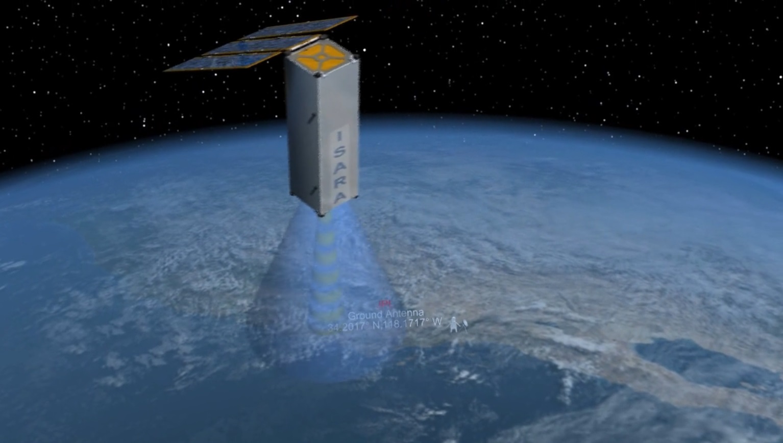
ISARA – the Integrated Solar Array and Reflectarray Antenna – is a technology demonstration CubeSat mission undertaken by NASA’s Jet Propulsion Laboratory to demonstrate a Ka-Band reflectarray antenna that will boost data rates for small-satellite missions from a baseline of 9.6kbit/s to over 100Mbit/s while doubling as a solar array – combining two essential satellite functions into one integrated system for a modest increase in spacecraft mass and complexity.
Data budgeting and power generation have become two fundamental issues for CubeSat missions: sensors like cameras, meteorological instruments and onboard computing elements have reached a stage of miniaturization where small CubeSats can generate a data volume matching that of flagship satellite missions. However, at the present stage of technology, only very few CubeSat missions employ high-speed communication terminals exceeding a few Mbit/s.
The development of an integrated solar array / antenna reflector for CubeSats can solve these two fundamental issues and pave the way to high-performance CubeSat missions in various operational and scientific areas. With the technology demonstrated by ISARA, a modest increase in mass, volume and cost could enable a hundredfold increase in data capacity, allowing advanced CubeSat concepts to be realized.
ISARA is a JPL-led mission conducted in close cooperation with CubeSat platform supplier Pumpkin Inc, and the Aerospace Corporation. The mission employs a five-Kilogram, 3U CubeSat and comes with a total development cost of $5.5 million, funded through the Small Spacecraft Technology Program of NASA.
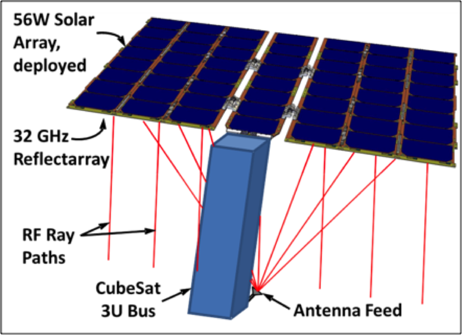
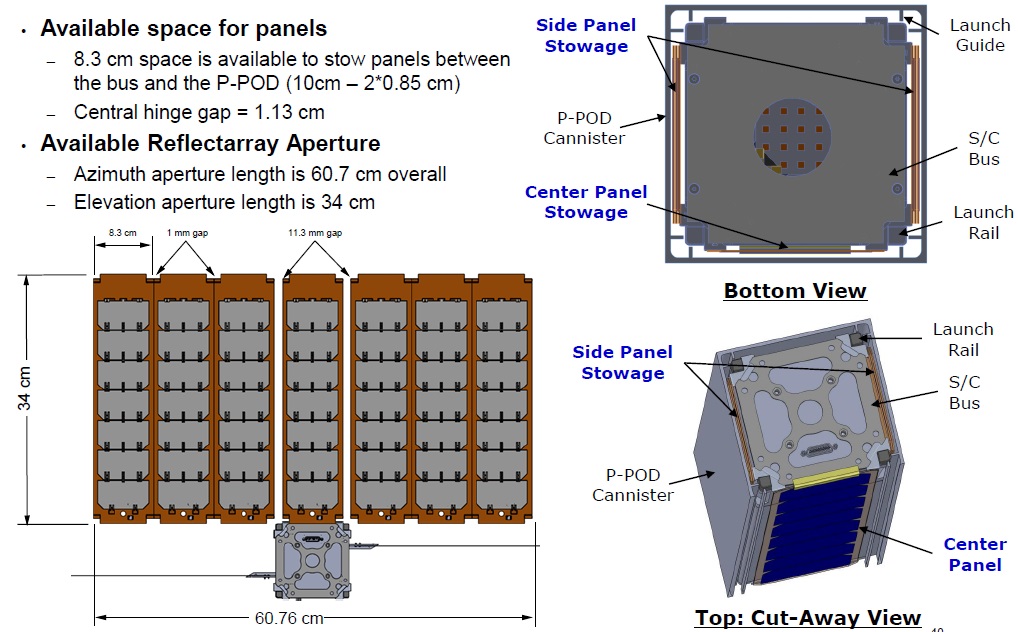
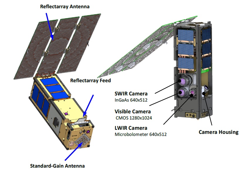
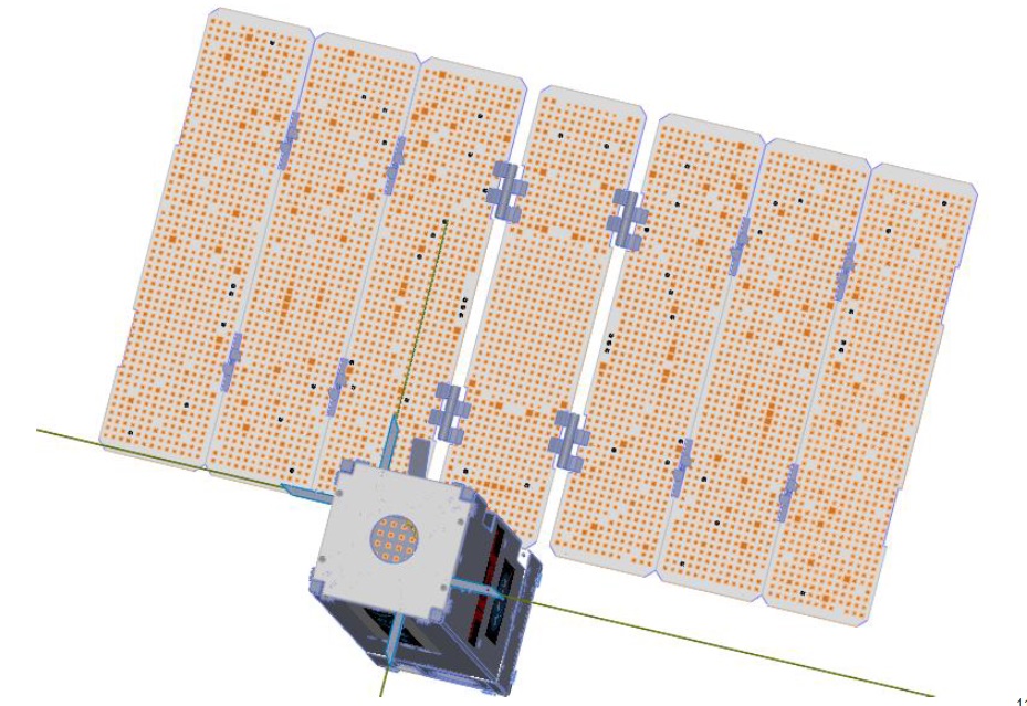
The key to ISARA’s technical advance is the combination of a high-gain Ka-Band reflector antenna with an existing solar panel design. This combined panel consists of seven 3U side panels, each 10 by 30 centimeters in size, to create a total antenna aperture of 30 x 70 centimeters on the underside while the upper side facilitates the UTJ Gallium-Arsenide solar cells for a power generation of 56 Watts. The array structure employs Pumpkin’s Modular Deployable Solar Array System.

The reflectarray antenna design is a relatively new type of antenna, consisting of standard printed circuit boards with an array of square copper patches etched into them. These metallic patches collimate divergent rays from a small feed antenna into a focused beam, essentially behaving like a parabolic reflector to deliver a directed beam. Because conventional solar arrays are made of a similar printed circuit board material, the reflectarray can be printed directly onto the back of the solar panels, further reducing the mass of the dual-purpose system.
A small patch array deployed from the lower face of the CubeSat side panel on the antenna side completes the high-gain antenna system, outputting a 35dB gain at a frequency of 32 GHZ. The ISARA antenna elements are etched onto 12-mil Rogers RO4003 dielectric substrate and the 2 x 3-element patch antenna delivers a 100° x 50° illumination pattern for optimized taper and spillover efficiency as shown in computer simulations. The flat feed antenna resides on a spring-loaded hinge with coaxial service loop and automatically slips into its deployed position once the solar array enters deployment.
ISARA uses a MAI-400 attitude determination and control module provided by Maryland Aerospace to achieve a pointing accuracy of 0.2 degrees as needed for narrow-beam communications. MAI-400 is a 0.5-Unit stand-alone device that comprises three reaction wheels as main actuators, three electromagnets to provide de-tumble & reaction wheel desaturation capability and a three-axis magnetometer, Earth horizon sensors, MEMS Gyro and an additional Star Tracker acting as attitude sensors.
Operational communications with ISARA are handled via traditional low-rate UHF systems that are in use for the initial satellite checkout and commissioning phase before the Ka-Band experiments can begin. The Ka-Band demonstration will comprise three elements: data rate, antenna gain and antenna pattern. Data rate achieved for downlink will be measured and compared against estimated receiver noise, the antenna gain is determined by switching between the high-gain antenna and standard gain antenna.
Antenna pattern reconstruction is accomplished over several ground station passes with the satellite in fixed orientations so that the observation angle changes over the course of the pass. A number of pointing orientations will be used to obtain a sweep of cuts from which the pattern can be reconstructed.
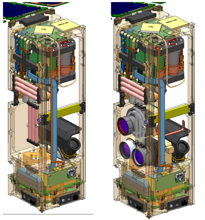
Since the ISARA communications payload only occupies a small volume within the satellite structure itself, there is plenty of volume for another payload that is filled up with the CubeSat Multispectral Observation System (CUMULOS), an experimental remote sensing system developed by the Aerospace Corporation comprising three Commercial Off-The-Shelf camera systems to capture multi-band imagery of Earth for potential future application in small weather satellites.
The CubeSat rideshare opportunity for CUMULOS was organized in a non-evasive architecture with CUMULOS remaining passive while the ISARA system undergoes testing (~3 months) to avoid any impacts with the primary mission.
CUMULOS hosts three separate camera assemblies: a) a visible (VIS) camera sensitive for wavelengths of 400-800 nanometers, b) a short-wave infrared (SWIR) camera covering a spectral range of 0.9-1.7 µm and c) an uncooled long-wave infrared camera (LWIR) covering wavelengths of 7.5 to 13.5 µm.
The visible camera assembly has a 17.4 mm focal length and uses a Silicon CMOS detector of 1280 x 1024 pixels (5.2 µm pixels), covering a footprint of 218 x 174 Kilometers and achieving a ground resolution better than 170 meters from the initial starting altitude of 500 Kilometers. SWIR uses a 25 mm lens and temperature-stabilized Indium-Gallium-Arsenide detector array coupled to an internal thermo-electric cooler. The detector has 640 x 512 pixels (25 µm), corresponding to an image footprint of 368 x 294 Kilometers and a ground sample distance better than 575 meters.

The long-wave infrared imaging system also uses a 25 mm / f1.1 lens and employs an uncooled microbolometer array of 640 x 512 pixels (17 µm), covering a ground footprint of 250 x 200 Kilometers and achieving a resolution better than 390 meters. Each pixel on the array consists of several layers including an infrared absorbing material and a reflector underneath it that directs IR radiation that passes through the absorber back to the absorbing layer to ensure a near complete absorption. As IR radiation strikes the detector, the absorbing material is heated and changes its electrical resistance which can be measured via electrodes connected to each microbolometer and processed into an intensity read-out.
CUMULOS will be operated as a small-aperture staring platform with the individual fields of view of the detectors placed within one another to achieve co-registration. Integration times will vary from detector to detector and read-out / analog-to-digital conversion will be performed with 10-bit quantization for VIS and 14 bits for the infrared channels.
Since CUMULOS will not employ the ISARA Ka-band radio, the instrument will be limited to the downlink of one to four full image triplets per day using a Software-Defined-Radio developed by the Aerospace Corporation as part of its CubeSat initiative. Thumbnails will be downlinked after image acquisition to help in the selection of images to be downlinked in full-frame raw, compressed JPEG or pixel-aggregated formats. An 8GB mass memory is available to hold imagery
The goal of the mission is to demonstrate a point-and-stare day-and-nighttime instrument with the added possibility of using the LWIR camera for cloud and land surface as well as sea surface temperature sensing. Attempts will be made to image dynamic weather events and characterize data using information from other satellites. Nighttime imaging of weather events is of particular interest to demonstrate a capability similar to the VIIRS day and night band realized in a much smaller payload.
