
Sentinel-3 Satellite Overview

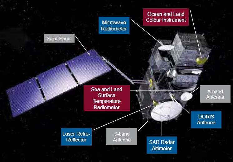
Within the framework of the GMES program, the Sentinel-3 mission is considered one of the most comprehensive given the satellite’s sensor payload that is capable of delivering relevant data for land, ice and ocean monitoring. The Sentinel-3 mission is designed as a two-satellite constellation for the provision of long-term operational marine and land-monitoring data.
As with the other Sentinel satellites, the Sentinel-3 mission was designed to support a high level of availability of data products and fast delivery times to users.
Sentinel-3 is primarily tasked with the collection of ocean and land color observation data at a revisit time of under four days and a quality matching that of previous missions. The satellites also collect global ocean and land temperature data with a revisit time of one day for single-look measurements and four days for more precise data. Furthermore, the spacecraft can deliver surface topography observations of land and ocean surfaces for the measurement of sea surface height, wave height over the ocean, and land surface elevation to cover ice regions. Data delivered by Sentinel-3 is also used in surface vegetation assessments with rapid Earth coverage.
The first two Sentinel-3 spacecraft, both built by Thales Alenia, are set for launch in 2016 and 2017 to make up the operational constellation in polar orbits spaced by 180 degrees. A third satellite is on order for launch before 2020 to provide an in-orbit backup to meet the needs for assured access to operational Earth observation data. ESA awarded the contract for the first satellite to Thales Alenia in 2008 with a total value of €305 million. A duplicate spacecraft, Sentinel-3B, was ordered from Thales in late 2009.
Sentinel-3A and 3B are based on Thales Alenia’s flight proven PRIMA satellite bus that provides a stable platform for the Earth observation payloads with respect to pointing accuracy, platform stability and support systems such as thermal control, power supply and data transfer. PRIMA first flew in 2007 aboard the COSMO 1 spacecraft with three more COSMOs following until 2010. The bus was also employed for the Radarsat-2 spacecraft launched in 2007 and has demonstrated its performance in flight. PRIMA is also utilized for the Sentinel-1 satellites which carry a Synthetic Aperture Radar Payload for day & night, all-weather ocean and land observations at high revisit times.
Spacecraft Overview
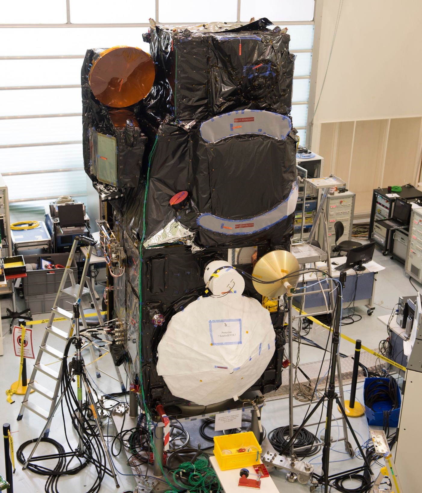
Overall, the Sentinel-3 bus measures 2.20 by 2.21 by 3.71 meters in size, outfitted with one deployable solar array. The spacecraft has a launch mass of 1,244 Kilograms including 120 Kilograms of propellant. Each Sentinel-3 satellite is designed for an operational life of 7.5 years, but carries sufficient propellant for a five-year mission extension and de-orbit maneuvers at the end of the mission.
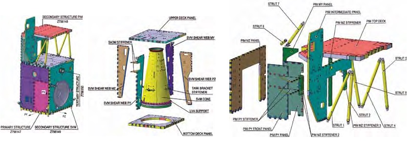
The bus structure is box-shaped and uses aluminum sandwich construction for its external panels and a series of internal panels that are attached to a Carbon Fiber Reinforced Plastic central tube and shear webs. The shear webs only accommodate the satellite’s reaction wheels while all other components are mounted on the inside of the external panels. The fuel tank occupies the majority of the lower-inner part of the central structural tube.
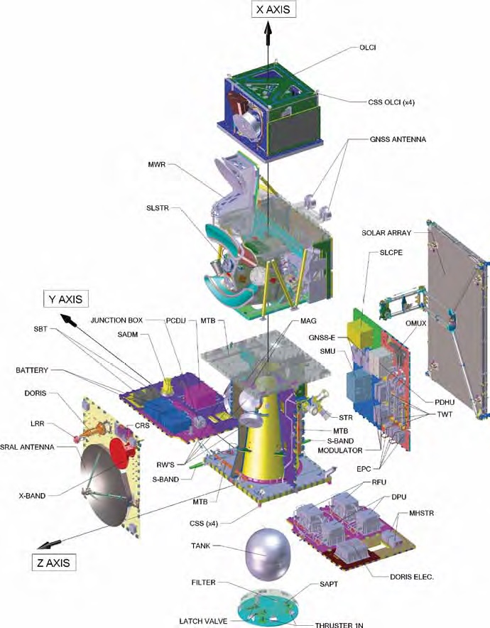
Sentinel-3 follows a modular approach – the payload systems are installed on a dedicated structure allowing them and the satellite platform to be built separately before the integration of the spacecraft. The satellite platform provides thermal control, attitude determination and control, propulsion capability, power supply, data handling and communications capabilities.
The Service Module is integrated into the cone section interfacing the satellite with the launch vehicle adapter while the Payload Module is mounted on the Service Module allowing the allocation of payload units & appendages through four lateral panels and the upper deck of the satellite.
The central tube and shear webs consist of aluminum honeycomb with multiple Carbon Reinforced Polymer Skins. External panels feature aluminum surfaces to provide an efficient thermal pathway for heat rejection.
Electrical Power System
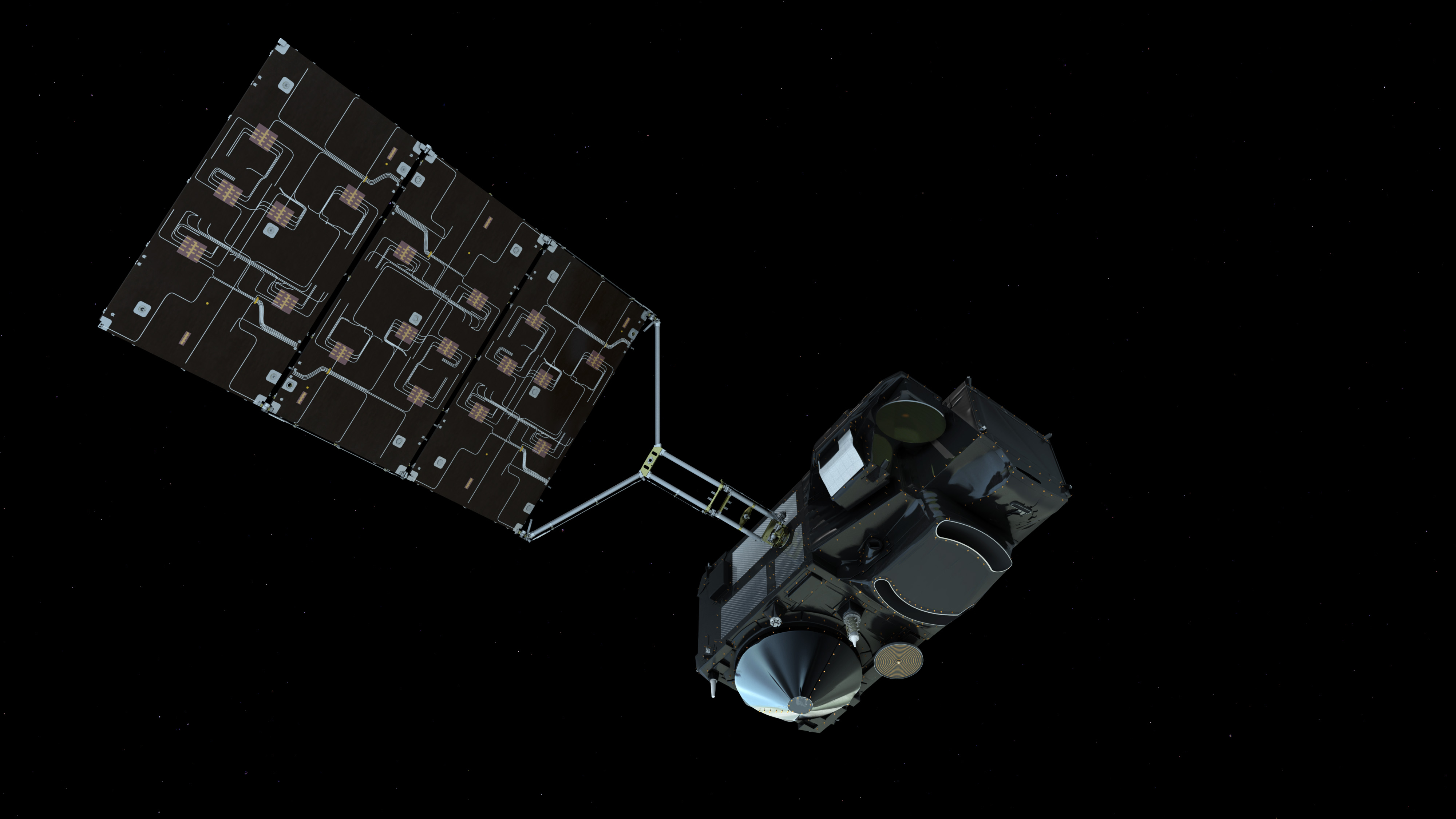
Sentinel-3 uses a single solar array wing with three panels to generate electrical power with Gallium-Arsenide triple junction solar cells, producing a total power of over 2,000 Watts at the start of the mission, dropping to 1,960 Watts at the end of the nominal mission.
The array has a total surface area of 10.5 square meters. Spring-loaded hinges deploy the panels once in orbit and the array has a Solar Array Drive Mechanism that rotates it to face the sun whenever possible. The drive assemblies are controlled by the spacecraft controller based on Sun Sensor Data.
The solar array is canted by 30 degrees to optimize sun exposure in the satellite’s Sun-Synchronous Orbit. The 8 by 4-centimeter solar cells are arranged in 22 strings and the three panels host six shunting sections, grouping seven strings for a total of 2,772 solar cells.
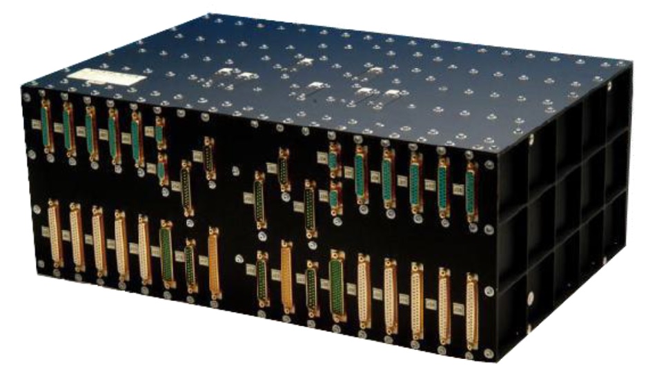
The Power Conditioning and Distribution Unit controls the state of charge two Li-Ion batteries with a combined capacity of 168 Amp-hours, making use of Multi-Standard Cells. Sentinel-3 employs an unregulated power bus, dependent on the battery output voltage varying between a minimum ‘end of discharge’ and a maximum ‘end of charge’ value. This requires all components receiving power to have their own regulation systems, a design chosen to limit the mass of the Power Conditioning and Distribution Unit (PCDU).
The Sentinel-3 PCDU can support a bus power of 500 to 6500 Watts and is in charge of battery charge management featuring cell charge balancing and by-pass actuation. It delivers power between 22 and 37 Volts depending on current battery charge status.
It is also in charge of commanding pyro devices used for deployment events and actuates the spacecraft heaters. Five grades of Latch Current Limiters provide power bus protection.
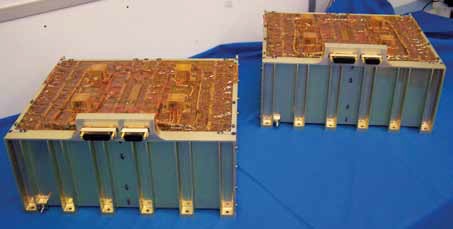
The 35 by 20- centimeter PCDU is connected to the spacecraft computer via 1553 and RS-422 data buses. Internally it consists of a backplane onto which the required power modules are stacked to enable the system to be catered to specific mission needs.
The Sentinel-3 PCDU can support a direct transfer of power from the solar array onto the power bus by regulating the current delivered by the solar array through shunting solar cell strings, allowing the satellite to keep its battery fully charged and operate from solar power when in illumination. The PCDU delivers four power lines, one to the bus users, one to the payloads, a dedicated heater line and a pyro line.
The battery assembly is comprised of two identical modules each with 56 strings of battery cells. A Disconnect Mechanism is used to provide cell over-charge protection and a shut-down separator consisting of micro-porous polyethylene layers provides battery protection. To avoid battery-related explosions, the cells are equipped with aluminum burst disks to vent pressure in the event of a failure.
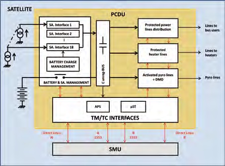
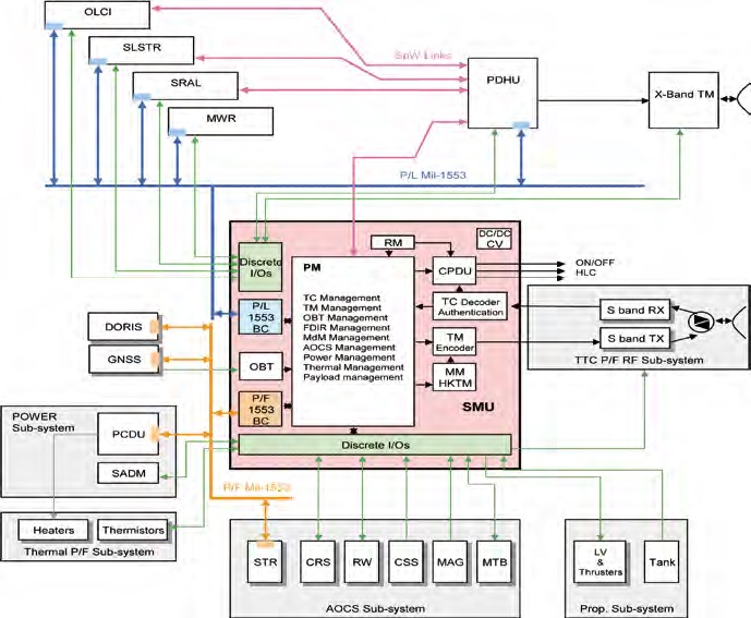
Sentinel-3 Functional Block Diagram
Propulsion System
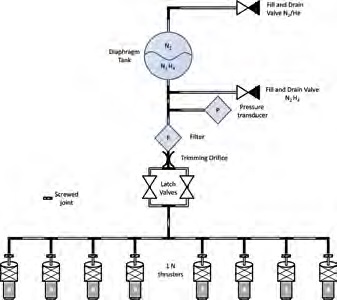
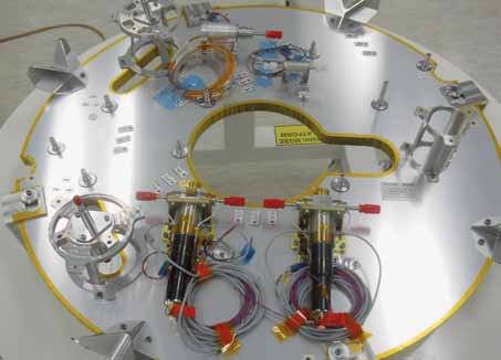
Sentinel-3 is equipped with a monopropellant propulsion system consisting of 8 thrusters divided in two banks of four thrusters. The thrusters are installed on a dedicated propulsion panel mounted on the aft side of the spacecraft. The main purpose of the propulsion system is to deliver delta-v burns for orbit corrections and maintenance as well as deorbit maneuvers at the end of the mission.
The Propulsion System uses a large propellant tank that is installed in the central aft portion of the satellite to maintain the vehicle’s Center of Gravity once the propellant is expended. The tank can hold up to 128 Kilograms of Hydrazine and is pressurized with gaseous Nitrogen. An elastomeric diaphragm inside the tank insures that the propellant is supplied to the engine without any gas bubbles and the diaphragm tank design also ensures very little propellant sloshing to support high-pointing stability during nominal spacecraft operations.
Between the tank and the thruster bank is the main pressure transducer, a propellant filter and a dual latch valve. Each of the 1-Newton thrusters has two valves using dual-series seats and dual coils. The thrusters generate thrust by the catalytic decomposition of hydrazine propellant using heated platinum/palladium catalyst beds.
The propulsion system is operated in blowdown mode starting at a tank pressure of approximately 24 bar. The thrusters can tolerate supply pressures of 5.5 to 23 bar to generate a thrust of 0.36 to 1.45 Newtons. The corresponding specific impulses are 205 seconds at the lowest supply pressure and 221 seconds at the highest pressure. Each thruster assembly weighs about 0.23 Kilograms and can be operated in steady-state mode for orbital maneuvers and pulse mode for attitude control.
Attitude Determination and Control System
Sentinel-3 relies on an number of sensors to precisely determine its attitude in order to fulfill the precise pointing requirements for this type of mission. Because of the high-stability needed by the instrument payload, Sentinel-3 has to use a low-vibration system with particular focus on gyroscopes and reaction wheels. In its nominal mission mode, the satellite has to precisely point its Earth-facing deck towards the planet for the instruments to collect data and face the solar panel towards the sun for proper power generation while also ensuring the radiators are pointed to space.

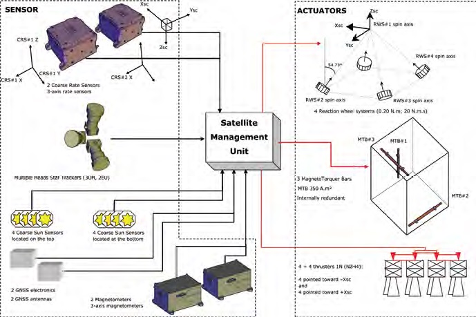
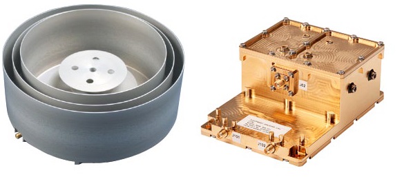
The primary rate sensor on the Sentinel-3 satellite is a newly developed MEMS gyroscope – a vibrating structure gyro system featuring a silicon ring fixed to a structure in which vibration is induced using a small electric current. Lateral motion of the ring – caused by coriolis force – can be measured to deliver a signal proportional to the rate of motion along the sensitive axis. To measure rates along all three axes, the satellite combines three MEMS units, each measuring 11 by 11 by 7 centimeters in size and weighing 750 grams. Because this is the first time this type of sensor is deployed to space, Sentinel-3 has a backup system to ensure redundancy.
The rate sensors are primarily used during rate dampening to deliver data on body rates that need to be brought down so that the more precise optical sensors can pick up attitude data.
Sentinel-3 is outfitted with eight Coarse Sun Sensors – photodiodes installed on each of the eight corners of the spacecraft to measure the intensity of sunlight hitting each of the diodes in order to determine the solar vector. Each sensor has a field of view of 160 degrees and is very compact in size at 3 by 3 by 1.5 centimeters. This arrangement of photodiodes is sufficient for very crude attitude determination, typically used in a spacecraft safe mode case to ensure the solar array continues to point towards the sun.
A three-axis, cold redundant magnetometer will keep track of angular rates by measuring the time derivative of the measured magnetic field vector along the spacecraft body axes.
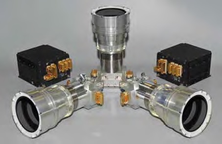
The primary attitude determination system is a Star Tracker with three optical heads and redundant data processing units, collecting imagery of the sky analyzed by a software algorithm that compares the acquired star pattern with a catalog to precisely determine the spacecraft’s orientation in space.
Each of the three optical heads weighs 1.4 Kilograms and measures 14.5 by 28.3 centimeters in size, outfitted with a baffle to reject stray light from the sun and Earth. Light is focused by an radiation hardened glass onto a thermoelectrically-cooled Active Pixel Sensor for detection. A spacewire interface is used to transmit raw signals from the optical heads to the electronics unit. The EU includes a power converter and processor required to control the operation of the optical heads and process the signal output into attitude frames. It weighs 1.9 kg and takes of 17.0 by 14.5 by 10.3 centimeters.
The sensor is capable of acquiring attitude frames in less than 2.5 seconds provided attitude rates are below 8 degrees per second. The sensors can deliver up to 30 attitude frames per second and can tolerate the moon within their field of view. The star tracker delivers pointing knowledge of up to 30 µrad.
The main attitude actuation system of the Sentinel-3 satellite is a Reaction Wheel Assembly with four reaction wheels installed on the internal shear webs, delivering redundant control on all three axes. The reaction wheel assembly is a rotating inertial mass – when accelerating the wheel, the satellite body to which the wheels are directly attached will rotate to the opposite direction as a result of the introduced counter torque. Three magnetic torquers are used to counter the resultant force when de-spinning the reaction wheels as part of regular momentum dumps.
Orbit Measurement Systems – GPS, DORIS & LRR
Sentinel-3’s mission requires the satellite to be kept in a precise orbit and, for instrument data processing, its location above ground has to be known and recorded at all times.
Sentinel-3 is equipped with a 24-channel, dual frequency (L1 & L2), cold redundant GPS receiver for on-board orbit determination and to deliver precise timing solutions. Additionally, GPS data will be recorded for downlink to the ground for science data processing. The GPS unit calculates the real-time position of the satellite to be recorded for proper geo tagging of science data. GPS data is also interpolated into attitude determination, using it to keep track of Earth’s rotation and sun ephemeris to compute the optimized position of the solar array wing at all times.
Through real time GPS orbit determination, Sentinel-3 can calculate its orbit to within 3 meters. Ground processing of recorded GPS data will yield an orbit calculation with an accuracy better than 3 centimeters.
DORIS – the Precise Orbit Determination System – uses a ground network of 60 orbitography beacons located all over the globe. These beacons send out signals at two frequencies which can be received by a satellite. Because the satellite moves at a fast speed, it causes a Doppler shift in the signal frequency that can be detected and used to calculate the satellite’s velocity when the two frequencies are precisely known. Collecting several measurements of the satellite’s velocity over different beacons allows data to be assimilated and used in orbit-determination models to constantly re-calculate the satellite’s orbit and its position with an accuracy of three centimeters. Precise knowledge of the satellite’s position above Earth is critical for proper geo-locating the radar and radiometer data.
The DORIS instrument aboard the Sentinel-3 satellites hosts a new generation DGXX-S receiver that builds on lessons learned from earlier missions. Improvements in the calculation model include the solar panel position as well as the albedo and infrared pressure effects on the satellite at different solar panel settings. A number of prediction models such as Ultra-Stable Oscillator frequency drift and along-track acceleration are being used on the newer system for more accurate calculations of satellite position.
DGXX-S consists of a dual-frequency omni-directional antenna and a twin receiver that performs Doppler measurements and receives auxiliary data from the beacons. The system includes two Ultra-Stable Oscillators to deliver timing solutions. DGXX-S allows seven channels to be tracked simultaneously to achieve an accuracy of 3 millimeters in the range measurement. The system is relatively compact in size with a mass of just 1.15 Kilograms compared to first generation systems that weighed in at 18 Kilograms.
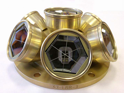
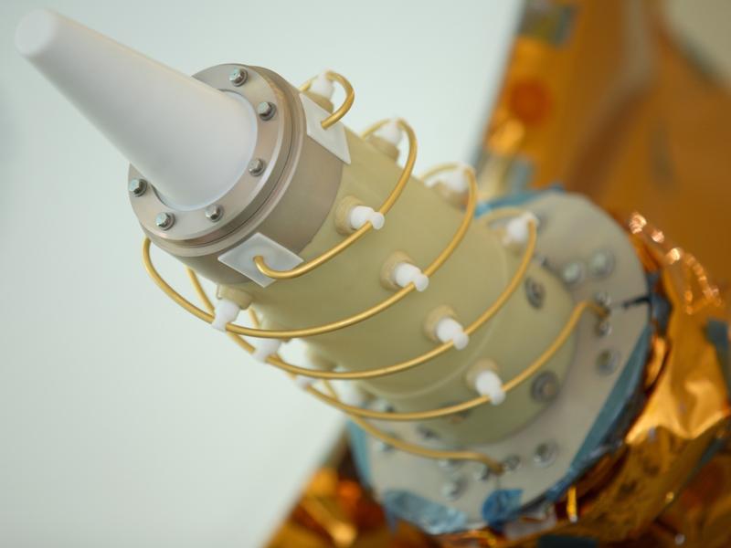
Furthermore, for precise orbit determination, Sentinel-3 hosts a Laser Retroreflector as a reference target for satellite laser ranging measurements. The LRA also comes into use for the calibration of the altimeter, completed at regular intervals. It resides on the nadir side of the spacecraft and hosts nine quartz corner cube arrays as a truncated cone – one corner cube reflector resides in the center while the other eight are distributed azimuthically around the cone. This arrangement permits laser ranging at all angles of a 360-degree field of view in azimuth and 60° in elevation. The individual reflectors have been optimized for a wavelength of 532 nanometers (green visible light) and offer a field of view of 120 degrees. The entire reflector assembly, a passive payload, has a mass of around 2 Kilograms.
Using laser ranging, the satellite altitude can be determined to within a few millimeters, making this system the most accurate orbit determination tool aboard the Jason-3 satellite. Though, laser ranging is not available continuously and therefore other systems that are more easily in operation and require less support are used on the satellite. Laser ranging is only supported by few ground stations worldwide and weather plays a considerable factor for this type of altitude measurement.
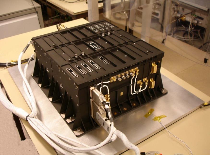
Command and Data Handling
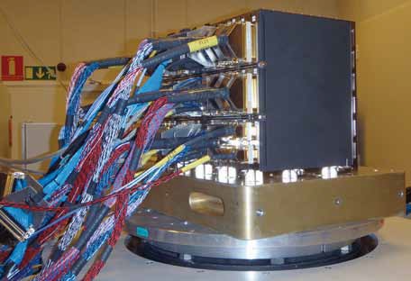
The heart of the Sentinel-3 spacecraft is an internally redundant Satellite Management Unit that is in charge of all onboard activities – command reception and execution, management of all onboard functions, commanding of science activities, generating status telemetry and downlinking satellite health data to Earth. A separate Payload Data Handling Unit accepts the high and low-rate data streams from the instruments, completes onboard processing tasks, stores data and transmits data to the communications system for downlink.
Payload data from the three high-rate instruments is collected through a SpaceWire Network to the Payload Data Handling Unit while low-rate data from the instruments is sent to the Satellite Management Unit using 1553 data buses. The SMU then relays the data to the PDHU via SpaceWire.
The PDHU can accept four SpaceWire connections at up to 100Mbit/s per line. The wire harness and internal communications architecture is redundant and the PDHU is fully cross-strapped between the prime and redundant strings. As interfaces with the SpaceWire bus, the instruments use Amtel Field Programmable Gate Arrays while the SMU employs Application Specific Integrated Circuits to fulfill the same purpose.
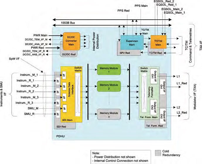
Payload data is stored in a 384 Gbit solid state mass memory with two memory units, capable of holding about two orbits worth of observation data. A third memory unit with 192 Gbit of storage is available as a redundant spare.
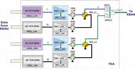
The Sentinel-3 satellite uses two communication links, an S-Band system to provide telemetry downlink and command uplink and a high-speed X-Band system for the transmission of science data. S-Band uplink occurs at a data rate of 64kbit/s while downlink reaches 1024Mbit/s in nominal mode. A contingency downlink option exists at 128kbit/s. The nominal downlink uses quadrature phase modulation while the contingency signal is binary modulated. The S-Band system uses two transponders for redundancy and two antenna assemblies. The X-Band terminal supports two downlink channels, each operating at 280 Mbps.
Thermal Control System
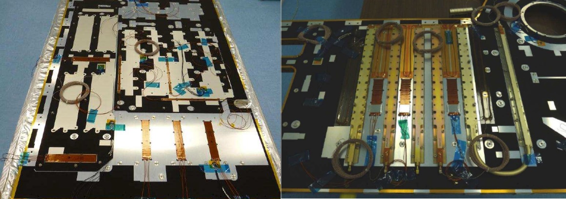
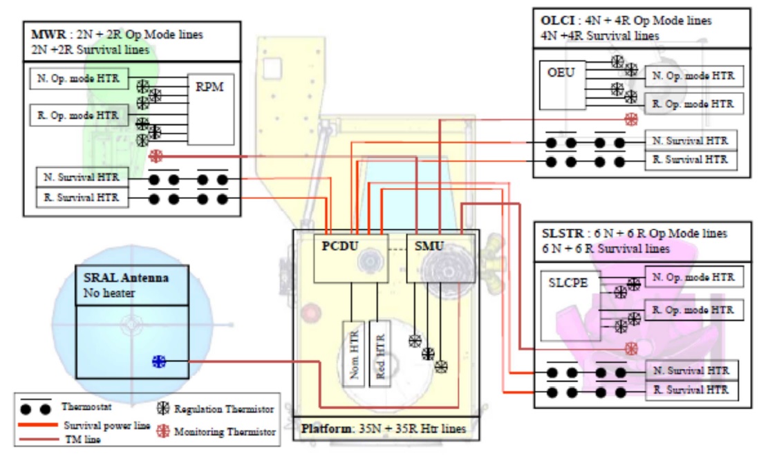
Sentinel-3 uses a combination of active and passive thermal control systems. Passive thermal control is accomplished by using multilayer insulation (MLI) covers and MLI tents to protect all components that reside inside and outside the spacecraft body. A number of heaters are directly attached to the spacecraft components such as avionics boxes, propellant tanks, thruster valves and motor assemblies. Several thermistors provide temperature readings to the command system of the spacecraft in order to activate or deactivate the heaters. Commanding is provided by the SMU based on fixed thermal setpoints that can be reprogrammed in flight.
The primary design philosophy of Sentinel-3’s Thermal Control System is to decouple all payload components from the satellite platform and manage their thermal situation independently. In nominal satellite operations, each payload is individually responsible for managing its own thermal state within the overall boundary conditions, such as keep alive temperatures, provided by the spacecraft.
Internal heat rejection from the spacecraft is accomplished through the lateral panels that feature Second Surface Mirrors for optimized heat rejection. Heat dissipation surfaces reside on the -Z, and +/-Y faces of the satellite that are pointed away from the sun and Earth, facing deep space when the satellite is in its working attitude.
The Multilayer Insulation of the external and internal components is comprised of aluminized Kapton and Mylar layers separated by polyester spacers. Inside the spacecraft, heat radiation exchange is controlled through the use of high infrared emissivity coatings on the inside of the lateral panels to absorb heat that is then radiated to the outside.
Components on the internal panels have thermal fillers underneath the baseplates and excess heat is transported via doublers or heat pipes of different shapes to reach the radiators.
Components that generate large heat loads such as the Satellite Management Unit and the Payload Data Handling Unit are connected to heat pipes filled with ammonia as working fluid to transport excess heat to radiative surfaces on the exterior.
