Chang’e 5 Test Mission
The Chang’e 5 Test or Precursor Mission (Chang’e 5-T1) is China’s next step in its lunar program to pave the way to sample return missions to the Moon as early as 2017. Chang’e 5-T1 will demonstrate a re-entry capsule at realistic re-entry speeds that would occur on a lunar sample return mission. For that, Chang’e 5-T1 will conduct a circumlunar flight with a duration of eight days – launching from China on October 23, 2014 and entering a circumlunar Free Return trajectory back to Earth for landing on October 31/November 1.
China laid out its lunar plans in the early 2000’s, identifying three phases of the country’s lunar project – I) complete orbital missions to study the lunar surface, II) conduct a soft landing on the Moon’s surface with a lander and rover, and III) return sample material from the lunar surface as part of a robotic mission.
Phase I and II have been completed by the Chinese over the past years celebrating great successes with the Chang’e 1 and 2 lunar orbiters and the Chang’e 3 lander and rover. Work is currently underway to fulfill the objectives of Phase III with one or two lunar sample return missions before 2020.
China’s Previous Lunar Endeavors
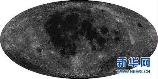
The Chang’e 1 mission was China’s first lunar orbiter that was launched by a Long March 3A rocket in October 2007 and operated in lunar orbit for one year and four months, performing remote sensing operations using an instrument payload consisting of a high-resolution stereo camera, an imaging spectrometer, a laser altimeter, Gamma and X-Ray spectrometers, a microwave radiometer and a particle detector. The spacecraft provided a high resolution map of the Moon and a wealth of scientific data including data on the chemical composition of the lunar surface and the particle environment of Earth and Moon.
Chang’e 2 launched in 2010 atop a Long March 3C and had a similar mission, but was equipped with improved instruments including an improved stereo camera, a laser altimeter, gamma- and X-ray spectrometers and a microwave sensor.
The craft successfully conducted science operations in lunar orbit from October 2010 to June 2011 before departing lunar orbit and beginning an ambitious extended mission, conducting a transfer to the Earth-Sun L2 Lagrangian Point for testing of the Chinese deep space tracking equipment and to demonstrate the operation of deep space missions.
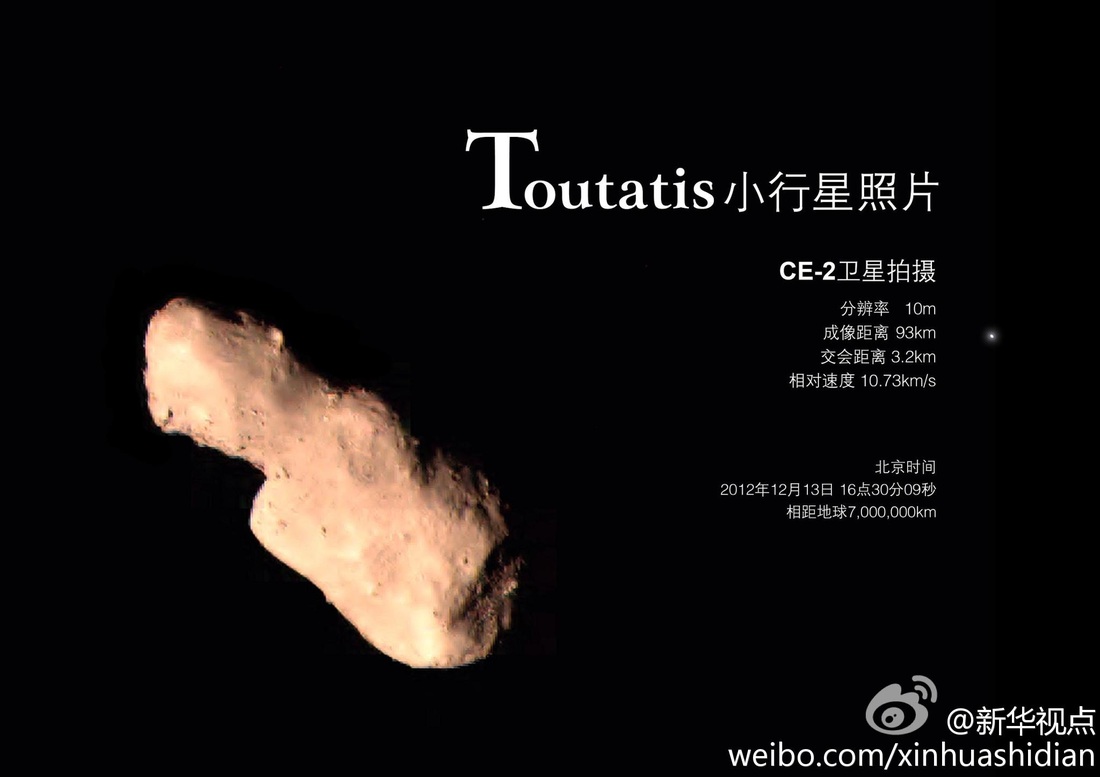
In April 2012, Chang’e 2 departed L2 and headed for a close flyby of asteroid Toutatis that was completed on December 13, 2012 with Chang’e coming as close as 3.2 Kilometers – returning data and imagery as well as valuable lessons learned for the operation of deep-space missions. As of early 2014, Chang’e 2 was still operating and teams were hoping that the craft could continue functioning until passing 300 Million Kilometers to Earth.
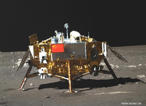
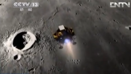
Building on the success of the two lunar orbiters, China embarked on the most ambitious lunar mission to date in December 2013 – launching the Chang’e 3 lunar lander and Yutu rover atop a Long March 3B lifting off from Xichang. The probe successfully entered lunar orbit five days after launch and began its descent to the surface on December 14. Successfully touching down in the Sea of Rains, Chang’e 3 became the first craft to make a soft landing on the Moon in 37 years.
Shortly after landing, Chang’e 3 released the small Yutu rover that explored the lunar surface for four weeks before suffering a structural defect that rendered its mobility system useless. Despite being immobile, Yutu continued to send data back to Earth way past its original design life of three months – still operating after more than ten months on the surface of the Moon. Outfitted with a UV Telescope to observe stars and an extreme UV sensor to study Earth, the Chang’e 3 lander was reported to continue its one-year planned mission as of mid-2014.
A Step-by-Step Approach
Outlining its lunar plans, China was set on a path of missions gradually increasing in complexity with each flight building on elements tested and verified in a previous mission to reduce risk and ensure an overall success of the program.
Even beginning with the very first Chang’e mission, China was flying technology that was demonstrated before by building the spacecraft around a well-proven satellite bus that flew many times on orbital missions starting in the 1990s thus reducing risk from a spacecraft platform side, only leaving uncertainties on the payload and trajectory which became the prime objectives of the first mission. Additionally, China always planned two attempts for each mission with a backup vehicle in the planning for every flight. Chang’e 1 was backed up by Chang’e 2 that would have fulfilled its role should anything have gone wrong during China’s first orbital mission to the Moon.
With Chang’e 1 and 2 demonstrating trajectories to get to the Moon and delivering valuable data that helped pick potential landing sites, China was ready for a landing attempt. Again looking ahead, the Chinese planned for two shots at landing with Chang’e 4 identified as an identical mission as Chang’e 3 that would fly if the first landing mission had failed, implementing lessons learned.
Chang’e 3 also served as a precursor for future sample return missions by testing out a lander that could carry much more than the small 120-Kilogram Yutu rover to the lunar surface – a clear sign that China was thinking ahead again and devised its lander design to be suitable for sample returns from the start and therefore being able to test it on an earlier flight. Indeed, when looking at schematics and models of the Chang’e 5 spacecraft and comparing the lander with that of Chang’e 3, both landers match up in dimensions, landing system appearance and propulsion system design.
Testing for robotic rendezvous for lunar missions may have taken place as part of the Shijian-15 mission while a robotic capture was exercised using the Shiyan-7 spacecraft in the second half of 2013.
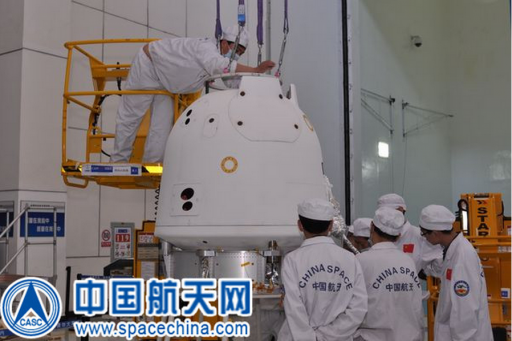
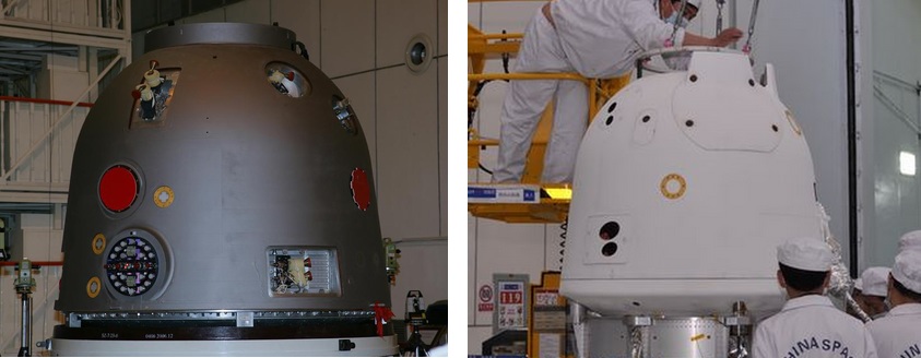
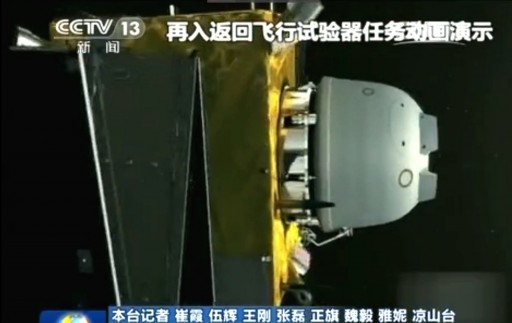
It would only be logical for China to use the upcoming sample return missions as a stepping stone for even more ambitious missions – perhaps even beginning to plan ahead for human missions to the Moon. Recent images that were released of the re-entry capsule of Chang’e 5 seem to confirm that reasoning, showing a capsule closely resembling a scaled-down version of the current Shenzhou spacecraft used in China’s human spaceflight program. Although the capsule used for Chang’e 5 and 5-T1 is too small for a human mission, the basic working principles and most importantly, heat shield technology suitable for entries at lunar return velocity could be tested to get a head start in the development of human missions to the Moon which are currently not on the agenda for the Chinese.
Comparison: Shenzhou & Chang’e Return Vehicle
China has stressed multiple times that no plans for human missions to the Moon exist, but officials indicated that such flights may be in the distant future, pending the successful conclusion of robotic Moon missions and the construction of China’s modular space station over the coming decade. The hints seen in the previous Chang’e missions indicate that China is aiming to be ready to initiate development for human missions to the Moon with plenty of prior knowledge should that path be chosen over the coming years.
Chang’e 5 Spacecraft Overview
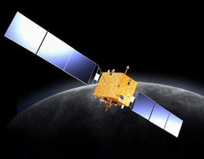
Chang’e 5 is China’s first lunar sample return mission and the most ambitious endeavor in the country’s lunar program, aiming to introduce completely new technologies and techniques such as a fully automated rendezvous in lunar orbit and sample transfers in between different spacecraft modules. As of 2014, Chang’e 5 was planned to launch in 2017 with its follow-up mission, Chang’e 6, planned two years later.
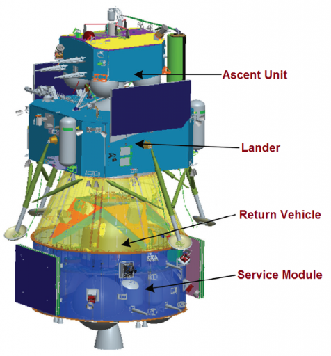
The Chang’e 5 spacecraft consists of four modules – a Service Module, a Return Vehicle, the Lander and the Ascent Vehicle. Overall, the spacecraft will have a launch mass around eight metric tons requiring a larger launch vehicle than previous missions. It is expected that Chang’e 5 and 6 will launch on the Long March 5 rocket that delivers the craft to a direct trajectory to the Moon.
The Chang’e 5 Service Module includes all systems to support the assembled vehicle on the way to the Moon, remain in lunar orbit for an extended period of time while surface operations are in progress, rendezvous with the ascent vehicle in orbit and support the Return Vehicle during the transfer back to Earth, setting up for re-entry.
The Service Module is equipped with power-generating solar arrays, communication systems for command uplink from Earth and telemetry downlink as well as a propulsion system and attitude control thrusters. Likely based on propulsion technology already used on Chang’e 3, the vehicle will use hypergolic propellants consumed by a throttlable engine (likely the 7.5kN engine used on Chang’e 3). The propulsion system of the Service Module would be used to conduct trajectory correction maneuvers on the way to the Moon, the lunar orbit insertion burn, orbital maintenance and the trans-Earth injection burn at the end of the mission.
The Service Module directly interfaces with the Return Vehicle that is installed in a cavity of the Service Module to reduce the overall length of the vehicle.
The Return Vehicle closely resembles the Shenzhou-capsule design in a scaled-down version. It is equipped with a modified heat shield to be able to withstand the re-entry into Earth’s atmosphere at speeds of 11 kilometers per second. Landing is accomplished using parachutes that are deployed during atmospheric flight, starting with a drogue followed by the main Chute. The Return Vehicle includes a thruster system to actively control its orientation before re-entry and modify its re-entry path by adjusting aerodynamic lift to target a reasonably sized landing zone. Onboard measurement systems and communication beacons for the location of the landed vehicle are also part of the entry vehicle.
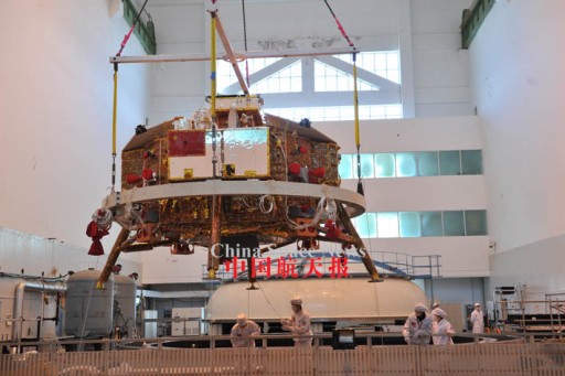
The Chang’e 5 lander in its structure is identical to the Chang’e 3 lander successfully demonstrated in 2013 with the obvious exception of ascent vehicle accommodations and surface sampling equipment that were not tested by Chang’e 3.
The lander has a dry mass of over one metric ton and a fueled mass of up to 3,800 Kilograms. Four primary landing legs are installed on the lander using a cantilever-type design with bumpers and interior buffer elements in the primary struts and multi-functional secondary struts that interface with the bottom panel of the lander. The legs will have to create a sufficiently soft landing after the main engine is cut off around four meters above the lunar surface.
The propulsion system will also be similar to that used by Chang’e 3 consisting of a main engine that can be throttled from 1.5 to 7.5 Kilonewtons to conduct a single continuous landing burn. Attitude control is provided by 28 thrusters providing thrust levels of 10N and 150N for three-axis control during orbital flight and the landing sequence. Power is delivered by two solar arrays that can be opened and closed on command. Navigation will be provided by an inertial guidance platform, a laser ranging system, an altimeter and an optical descent camera.
The Ascent Vehicle resides on the top deck of the lander using structural attachments to remain in place during orbital flight, landing and the surface mission. A central interface from the lander to the Ascent Vehicle is attached at the top of the vehicle using an arm that can be moved to the side to clear the way for the vehicle to launch from the top deck of the lander.
This interface includes electrical and data interfaces since the Ascent Vehicle will leave its two solar panels in a stowed configuration for the flight to the Moon and the surface mission. The interface also facilitates the sample transfer mechanism.
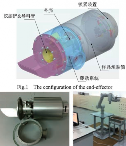
According to information published in Chinese papers, Chang’e 5 will use a four-degree of freedom robotic arm for the acquisition of regolith samples and small rocks that are delivered to the Ascent Unit by the robotic arm. The end effector of the arm includes a scoop for the acquisition of samples, a sample processing system using vibration and separation mechanisms that ensure that several individual samples can be acquired without coming in contact with each other. The entire End Effector containing the samples can be separated from the arm for the transfer to the Ascent Vehicle.
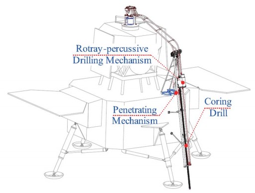
Additionally, the lander includes a coring drill and penetrating mechanism that will acquire one or more drill samples in the form of an intact core up to a depth of two meters making use of a rotary-percussive drilling mechanism. The drill core is delivered to the Ascent Vehicle inside a Kevlar tube that provides sufficient stability to protect the core while being flexible enough to be compacted in size for transfer to the Ascent Vehicle.
The Ascent Unit includes a main propulsion system built around a central main engine that is fired to lift off from the lunar surface, carrying the samples back into lunar orbit to link up with the Service Module – Return Vehicle stack using rendezvous sensors developed for the Shenzhou spacecraft including laser ranging and optical sensors.
The docking is accomplished using a claw-type docking mechanism. On the active side, three claws (spaced 120°) close when coming into contact with the passive side of the system that includes struts to be grasped by the claws to create a firm bond between the Ascent Unit and the Return Vehicle. The samples are then transferred to the Return Vehicle using a robotic system of currently unknown specifications.
After sample transfers are complete, the Ascent Unit is separated so that the Service Module can boost the vehicle out of orbit and carry the Return Vehicle back to Earth.
Chang’e 5 Mission Profile
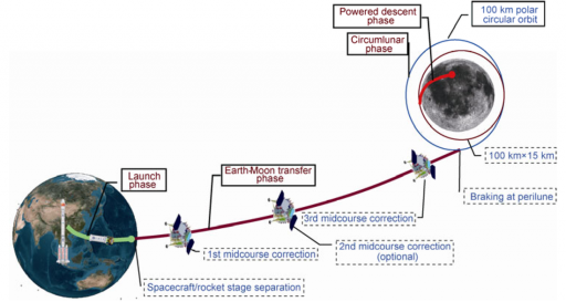
The eight-metric-ton Chang’e 5 stack will complete a complex mission that consists of eleven different phases and spacecraft configurations. The vehicle will be launched by a Long March 5 rocket blasting off from the Wenchang Satellite Launch Center that has recently finished construction. Delivered to a trans-lunar trajectory, the Service Module would perform adjustment maneuvers as needed to set up the appropriate conditions for lunar orbit insertion five days after launch.
The Service Module would be in charge of placing the stack into a circular orbit around the Moon at an altitude 200km (it is likely that a polar orbit will be used, similar to Chang’e 3). In that orbit, the Lander – Ascent Vehicle stack will separate from the Service Module in a one-time separation event likely using pyrotechnics. The Lander would use its own propulsion system to lower the periapsis to 15 Kilometers in advance of landing with the periselene location carefully positioned to line of with the landing site.
Landing will take place at the beginning of a Lunar Day (14 Earth days in duration).
The Lander will make one continuous landing burn using its main engine that actively throttles down as part of the descent. The 700-second landing sequence begins with a deceleration that takes the vehicle from 15 to 2 Kilometers in altitude transitioning to a quick Adjusting Sequence to move from horizontal flight to a vertical descent.
Coarse obstacle avoidance is completed before horizontal velocity is eliminated, setting up for a Hover Segment at 100 meters for image acquisition and fine-obstacle avoidance followed by a constant-velocity descent. At an altitude of four meters, the Lander will shut down its engine and drop to the surface.
It is likely that the aim of the mission is to complete all sampling and drilling operations within one lunar day to avoid risking hardware damage as a result of the harsh temperatures of lunar night. After sampling and transfers of up to 2 kilograms of lunar material to the Ascent Vehicle is complete, all preparations for the return journey will be completed.
The Ascent Vehicle will then use its propulsion system to ascend into an orbit of 15 by 180 Kilometers and further raise its orbit and complete a fully autonomous docking with the Service Module – Return Vehicle stack.
Sample transfers to the Return Vehicle take place in lunar orbit before the Ascent Unit undocks for a Free Flight in lunar orbit of at least ten days.
The Service Module would then conduct the trans-Earth insertion for a five-day flight back to Earth. 5,000 Kilometers from Earth, the Return Vehicle would separate from the Service Module for the final 20 minutes to re-entry.
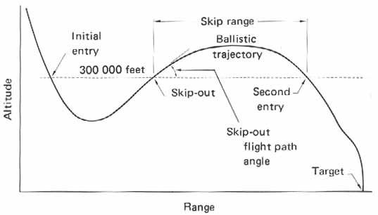
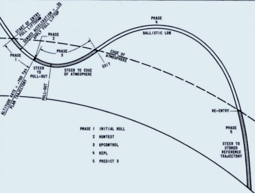
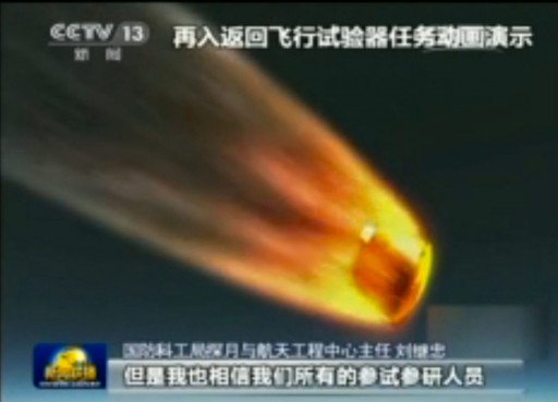
Re-entering at a speed up to 11 kilometers per second, the Return Vehicle would utilize a Skip Re-Entry that increases re-entry range, reduces the overall G-load on the vehicle and significantly reduces the thermal stress on the heat shield. Requiring precise guidance, a Skip Re-Entry consists of an initial dip into the atmosphere to reduce the velocity of the spacecraft that performs a pull-up maneuver to depart the atmosphere again and continue on a ballistic sub-orbital trajectory leading up to a subsequent entry into the atmosphere at a reduced speed for an atmospheric descent and a parachute-assisted landing.
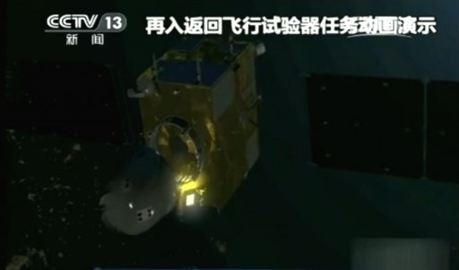
Chang’e 5-T1 Spacecraft Design
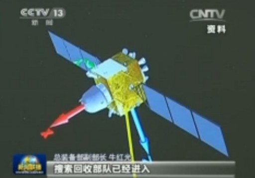
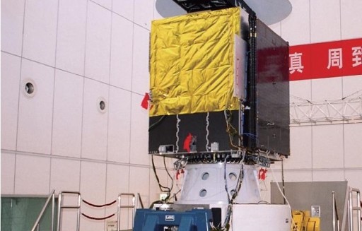
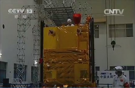
Since the sole purpose of the Chang’e 5 Test Mission is the demonstration of the Return Vehicle in realistic entry conditions, the mission does not require a full Chang’e 5 stack to be flown. Instead, the craft consists of a Service Module that utilizes the Chang’e 2 orbiter design with the Return Vehicle attached to it. The Service Module will support the Return Vehicle during the circumlunar mission and release it ahead of re-entry.
The Chang’e 5-T1 Service Module is based on the DFH-3 satellite bus manufactured by the China Academy of Space Technology and mostly used for Geostationary communication and navigation spacecraft, but also proved suitable for lunar orbit missions in the Chang’e 1 and 2 flights that both used this spacecraft platform.
DFH-3 has a dry mass of approximately 1,150 Kilograms and is capable of carrying up to 1,300 Kilograms of propellant. The satellite platform consists of a core body that measures 2.2 by 1.72 by 2.0 meters and contains all spacecraft systems including a bipropellant propulsion system, electrical power systems, attitude determination and control equipment, an onboard computer, communications hardware and cameras.
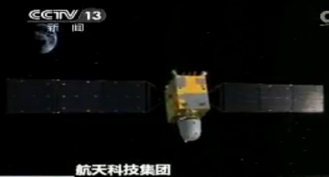
The satellite bus is equipped with two solar arrays, each consisting of three panels to generate a total power of 1,700 Watts (EOL) that is stored in Li-Ion batteries and distributed to all systems by dedicated EPS hardware that conditions the main power bus of the satellite. Using the three-panel arrays, the satellite reaches a span of 18 meters when deployed in space.
Each of the solar array panels is 3.3 by 2.36 meters in size creating a surface area of 7.8m². The gallium-arsenide solar cells have a beginning of life power output of 120 to 270 W/m². Solar panel deployment is accomplished after orbital insertion using pyrotechnic initiators.
The platform is three-axis stabilized using a series of navigation sensors that include Star Trackers, sun sensors and an inertial navigation platform to precisely measure body rates.
The star trackers acquire imagery of the sky that is analyzed by a software algorithm that compares the acquired star pattern with a catalog to precisely determine the spacecraft’s orientation in space. Each of the Star Trackers has a narrow field of view of 8.5 degrees, a focal length of 7.5 centimeters and an overall mass of 3.7 kilograms including electronics that connect the unit to the spacecraft’s RS-422 data bus. The star trackers acquire one frame per second and require low body rates for acquisition. The sun sensors can be used for coarse attitude control, pointing the solar arrays at the sun to ensure good power-generation.
Attitude control is provided by reaction wheels and the vehicle’s thruster system. The spacecraft is equipped with a bipropellant propulsion system using Monomethylhydrazine fuel and MON-1 (Mixed Oxides of Nitrogen) oxidizer. A 490-Newton engine is used for trajectory correction maneuvers while several 10N thrusters provide attitude control.
All satellite onboard operations are controlled by a Central Computer that likely uses one of CAST’s standard designs to deliver functions such as attitude computing and actuator commanding, command reception & execution, data storage, data/telemetry processing & downlink.
A Unified S-Band terminal is used for command uplink and housekeeping data downlink achieving low data rates of 1024bit/s for telemetry transmission and 125bit/s for command uplink. Chang’e 2 carried an X-Band payload that allowed the downlink of acquired imagery and instrument data at data rates of up to 12 Mbit/s.
Whether the Chang’e 5-T1 Service Module carries any instruments is not known. Looking at previous Chinese missions, it is likely that the vehicle carries a number of engineering cameras to monitor spacecraft operations such as the deployment of the solar arrays, the main engine, the separation from the launch vehicle and the separation of the Return Vehicle.
The Chang’e 5-T1 Return Vehicle is the key player in the Test Mission since the primary goal of the flight is the demonstration of the operation of the Return Vehicle, trajectory design and guidance, and the recovery after landing.
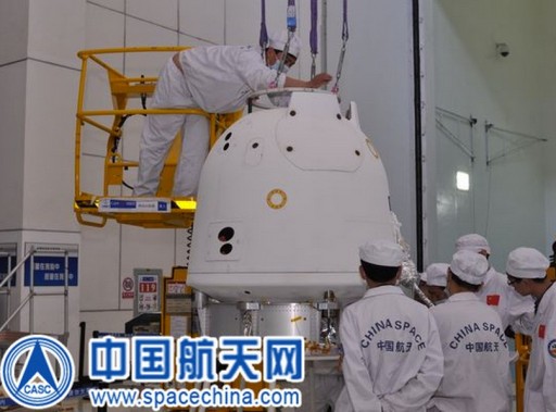
Photos of the Return Vehicle clearly show it being of a scaled-down Shenzhou-type design, closely resembling the exterior features of the Shenzhou that is used in China’s manned space program. On the capsule’s bottom side is the heat shield and on the top side is an access hatch and sample transfer mechanism that can be moved robotically to enable the transfer of sample material. The Return Vehicle includes batteries, an inertial guidance system, onboard control equipment, attitude control thrusters, communication systems, parachutes and most likely GPS sensors.
Judging from the only image released of the vehicle standing upright , the capsule is on the order of 1.5 meters tall.
Looking at its exterior, the capsule has a large parachute cover that is jettisoned pyrotechnically to deploy the parachutes of the vehicle. The capsule also has a series of thrusters to control its attitude in space and during atmospheric entry. The Shenzhou Entry Module uses eight 150N Hydrazine thrusters for attitude control, it is likely that a similar system is adopted for Chang’e, potentially with smaller thrusters.
The Return Vehicle will be receiving power from the Service Module for the majority of the mission to operate heaters and control systems and deliver housekeeping data to the Service Module.
The Return Vehicle facilitates different communication assets including beacons to help locate the vehicle after landing. Used for Chang’e is CAST’s S-Band Coplanar Ablation-Resistant Beacon that can operate in a broad temperature range. The cross-slotted and cavity-backed antennas send beacon signals at a frequency between 2.7 and 2.8 GHz at a bandwidth of 4 MHz to guide ground-based radar during re-entry and also provide beacon signals after landing.
The antenna is 13.6 centimeters in diameter and 9.2 cm deep, capable of operating at temperatures of up to 1,400°C allowing it to be installed on the side of the capsule where thermal loads will remain within that limit. Additionally, the Return Vehicle uses deployable UHF beacons that start operating after touchdown.
Precious Cargo
Taking advantage of a great scientific opportunity, China will not fly an empty vehicle around the Moon and back to Earth. Instead, the vehicle will be carrying a number of samples on a journey beyond Earth orbit to learn about the effects of the BEO environment on various organisms, seeds, plants and other samples. The sample containers will be loaded well before launch to complete a nine-day mission to space followed by extensive post-flight analysis.
Flying samples beyond the Earth environment and returning them to Earth has not been done over past years, only limited to Low-Earth orbit missions that returned samples back to Earth like International Space Station Experiments and the Russian Bion and Foton missions. China has also conducted a sample return mission as part of the Shijian-8 mission that launched in September 2006 and successfully returned to Earth after 15 days in orbit, carrying several thousand samples from a broad variety of plants including vegetables, fruit, grain and cotton to examine any changes to germination and plant physiology in space-flown plants compared to those grown on Earth.
An exact overview of the payloads aboard the Chang’e 5-T1 mission has not been provided.
Chang’e 5-T1 Mission Profile
Launch Vehicle & Ascent
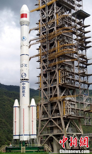
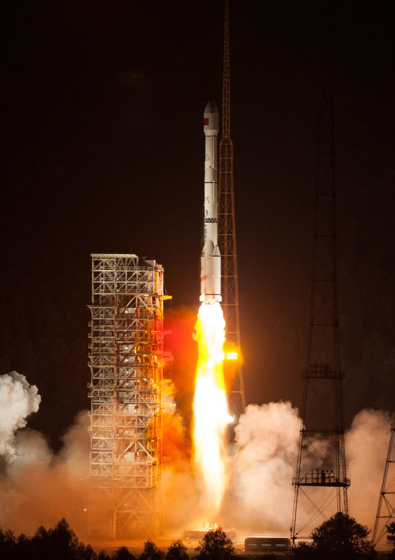
Liftoff of the Chang’e 5-T1 mission from the Xichang Satellite Launch Center is set for a window of just a few seconds at 17:59 UTC on October 23, 2014. Tasked with delivering the spacecraft on its path to the Moon will be a Long March 3C/E launch vehicle – the first of its kind to fly after conventional CZ-3C vehicles already launched ten times and the other vehicles of the CZ-3A launcher family are well-proven vehicles.
>>>Long March 3C/E Overview
The Long March 3C/E is a three-stage launcher with two boosters installed on the Core Stage to be able to boost payloads of nearly three metric tons out of Earth orbit. The differences of CZ-3C/E to the normal CZ-3C version are stretched boosters and a longer first stage, holding more propellant. CZ-3C(E) in itself is essentially identical to the Long March 3B(E) that launched the Chang’e 3 mission, simply subtracting two of the boosters.
Long March 3C/E weighs approximately 367,500 Kilograms and stands 56.33 meters tall with a core diameter of 3.35 meters. The boosters, first and second stage use storable propellants, Unsymmetrical Dimethylhydrazine and Nitrogen Tetroxide while the third stage uses cryogenic propellants, Liquid Hydrogen and Liquid Oxygen.
On Launch Day, the Long March 3C/E goes through a seven-hour countdown procedure that includes extensive launch vehicle checkouts and the cryogenic tanking sequence. The boosters, first and second stage are filled with storable propellants several days ahead of launch.
Telemetry and Communication Systems undergo final pre-launch tests at L-80 minutes. Flight Software load occurs at L-40 minutes followed by a verification of the Guidance & Control System of the vehicle. Also, the payload air-conditioning system is reconfigured and the purge system of the first and second stage is disconnected for launch. In the final 20 minutes of the countdown, the third stage engine begins its Chilldown Sequence to condition it for ignition. At L-15 minutes, the third stage propellant topping sequence begins followed by the disconnection of the spacecraft umbilical after the satellite has been placed in flight mode.
The telemetry system of the launcher goes into launch mode at L-3 minutes and one minute later, the umbilical arms to the third stage are retracted. 90 seconds before launch, the vehicle is switched to internal power and the control system of the vehicle assumes control of the countdown at L-1 minute. After a final set of systems checks, the engines of the boosters and first stage are ignited at T-0 with liftoff occurring an instant later.
Each of the two boosters measures 16.09 meters in length and 2.25 meters in diameter holding 41,100 Kilograms of propellant to be consumed by an DaFY-5-1 engine, a YF-20-type engine that provides 740.4 Kilonewtons (75,500 Kilogram-force) of sea level thrust. The two boosters will operate until T+140 seconds with separation occurring about two seconds after cutoff.
Following booster jettison, the first stage will continue powered flight on its own. It is 24.76 meters long with a diameter of 3.35 meters and a nominal fuel load of 186,200 Kilograms. First stage propulsion is provided by a DaFY-6-2 engine which is a cluster of four DaFY-5-1 engines that are also used on the boosters. The four engines provide a total sea level thrust of 2961.6 Kilonewtons (302,000 Kilogram-force). Vehicle control during first stage flight is accomplished by individually gimbaling the four engines.
After burning for 158 seconds, the first stage separates from the second stage in hot-staging mode, igniting the vernier engine of the second stage and then firing the pyrotechnic stage separation system to allow the second stage to pull away from the core.
Being 12.92 meters long, the second stage is loaded with 49,605 Kilograms of propellants that are consumed by a single DaFY-20-1 main engine and a four-chamber DaFY-21-1 vernier engine. The main engine delivers 742 Kilonewtons of thrust (75,660 Kilogram-force).
The four chambers of the vernier engine, each with a thrust output of 11.8kN, are gimbaled for three-axis control. The second stage main engine burns for 178 seconds while the verniers burn 6 seconds longer to accommodate the hot staging.
Just after passing the T+4-minute mark, the launcher will jettison the protective payload fairing, exposing the Chang’e 5-T1 spacecraft for the rest of its journey.
The separation between the second and third stage is accomplished using pyrotechnics and retrorockets on the second stage. Once the second stage is at a safe distance, the third stage ignites.
Long March 3C/E uses a cryogenic upper stage that provides re-ignition capability. Overall, the stage is 12.38 meters long with a reduced diameter of 3.0 meters. The third stage carries a total propellant load of 18,193 Kilograms of Liquid Hydrogen and Liquid Oxygen burned by a YF-75 cluster of two cryogenic main engines providing a total vacuum thrust of 156.9 Kilonewtons (16,000 Kilogram-force).
To deliver Chang’e 5-T1 to a trans-lunar trajectory, the third stage of the Long March 3C/E will conduct a two-burn mission, first boosting the stack into a Low Earth Parking Orbit followed by a second burn after a coast phase to set up the proper TLI conditions.
The first burn will be around five minutes in duration, aiming for a Parking Orbit around 200 Kilometers in altitude. Third stage cutoff is expected about ten minutes after launch to mark the beginning of a coast phase of under five minutes as the vehicle orbits over the Pacific Ocean. The second burn of the 3rd stage will be just over three minutes in duration to put the vehicle on a trans-lunar trajectory with an insertion velocity of 10.9km/s. Spacecraft separation occurs about twenty minutes after launch as Chang’e 5-T1 sets sail on a mission of a little over eight days.
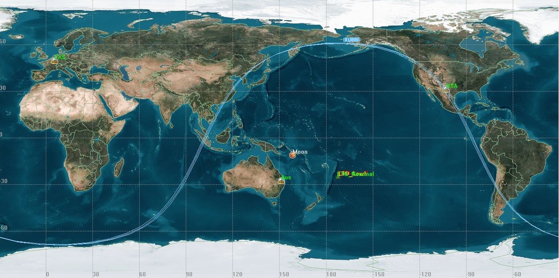
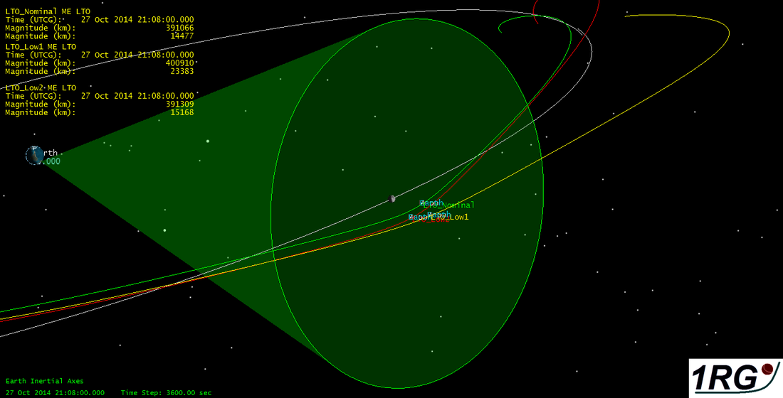
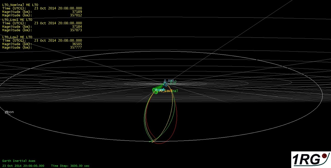
Trajectory
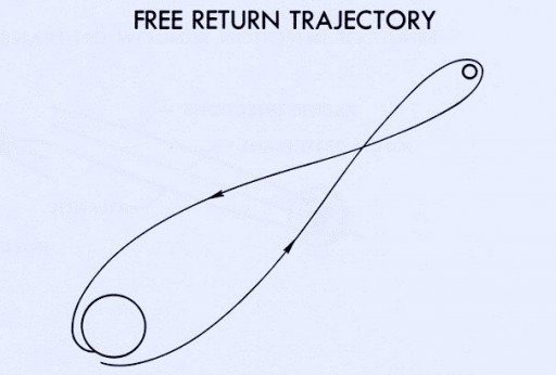
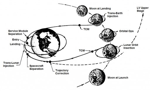
Chang’e 5-T1 uses a circumlunar free return trajectory which in theory is created only by the gravitation in a two-body system and does not require propulsion, although in practice, course corrections are needed to optimize the trajectory. With a spacecraft traveling away from a primary gravitational body (Earth), gravity due to a secondary body (Moon) causes the spacecraft to return to the primary body. The defining characteristic of a circumlunar mission is that the perilune (closest approach to the Moon) is located behind the Moon.
Free return trajectories were used by the Russian Zond lunar flights in the late 60s and early 70s as well as the Apollo 8, 10 and 11 missions. These three Apollo flights were inserted into a free return trajectory by design to protect for the event of a systems failure that left the vehicle without propulsive capability. Later Apollo missions switched to a hybrid trajectory entering a highly elliptical Earth orbit that would have delivered the craft to its entry corridor until all checkouts and the Lunar Module docking were complete at which point a course correction was made to target the Moon.
Apollo 13 switched back to a free return trajectory after the oxygen tank on its Service Module exploded, becoming the only Apollo craft to make use of a free return.
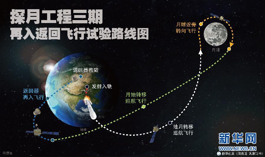
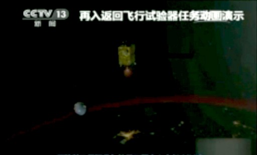
Chang’e 5-T1 is targeting an overall flight duration of eight days from October 23 to October 31/November 1 making its closest approach to the Moon in the night of October 27/28 (UTC). The upper stage of the Long March makes its closest approach 102.56 hours after launch. On the outbound leg, the craft can make several course correction maneuvers to adjust its path around the Moon, but more importantly, start targeting its re-entry location in order to be able to make an on-target landing in Chinese territory by modifying its flight duration so that the craft re-enters when Earth has rotated to the proper position.
The targeted perilune distance is 11,000 to 15,000 Kilometers. Not entering orbit, Chang’e 5-T1 will begin its return to Earth after passing behind the Moon once.
The return flight will again take approximately four days and could include more trajectory correction maneuvers to fine-tune the return path of the vehicle and precisely target the re-entry corridor chosen for the mission.
About 5,000 Kilometers from Earth, Chang’e 5-T1 separates the Return Vehicle from the Service Module to continue in Free Flight for 20 minutes ahead of re-entry. It should be noted that animations of the mission show the Service Module performing a main engine burn after the release of the return vehicle. It has not been specified what the final destination of the Service Module is – whether it will re-enter the atmosphere or attempt to enter an orbit around Earth or possibly a heliocentric orbit.
Re-Entry Demonstration
The major goal of the Chang’e 5 Test Mission is the demonstration of the Chang’e 5 Return Vehicle in an operational re-entry environment with a speed and trajectory matching that of the actual sample return mission to serve as a full rehearsal.
Chang’e 5-T1 will conduct a Skip Re-Entry that is more complex than a ballistic or gliding re-entry as it involves an initial re-entry during which the craft slows down, but lifts itself out of the atmosphere for a ballistic exospheric segment ahead of a second gliding entry that delivers the craft to a point where it can open its parachutes and land in a predictable zone on Earth.
Skip Re-Entry was utilized for the Russian Zond missions and studies were made for Apollo Command Modules after their return from the Moon. Despite being certified for the Skip re-Entry, Apollo used a re-entry mode that did not leave the atmosphere again, but included a pull-up segment.
Skip Re-Entries are used to reduce the heat load on the spacecraft, especially suitable for high entry velocities, however, the procedure requires very precise guidance making it very complex.
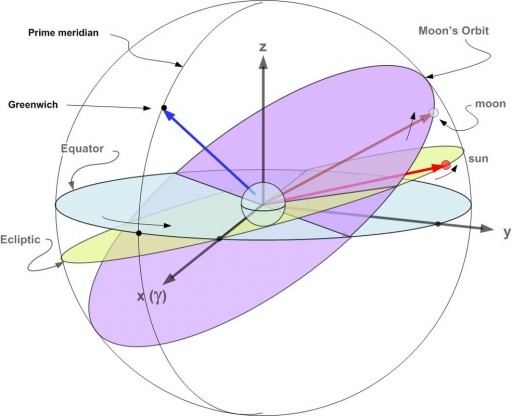
Targeting of a suitable landing site is a process that begins at launch since the targeting of the landing longitude depends on the flight duration as Earth rotates on its axis while the landing latitude is influenced by the Earth-Moon geometry and the rotation of the vehicle’s flight path relative to the Earth-Moon plane which is a function of declination. Chang’e 5-T1 will meet the Moon at its lowest declination which optimizes launch vehicle capability and also enables a landing at the desired latitude, north of the equator. Using a Skip-Entry, Chang’e 5 will have a long entry-range.
For an orbital mission around the Moon, the re-entry conditions are set up at trans-Earth injection, but for a circumlunar flight, the trajectory is determined at launch with limited course-correction capability along the way, primarily to adjust the landing longitude by varying the transit time.
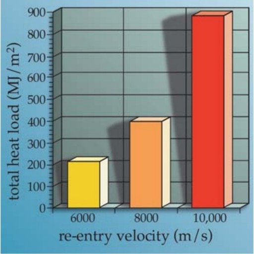
Coming back from the Moon and hitting the top of the atmosphere, spacecraft typically travels with a velocity of around 11 kilometers per second as opposed to 7.7km/s for a return from Low Earth Orbit. Simple physics show that an object entering at lunar return speed will have to dissipate a little over two times the kinetic energy of a LEO re-entry (E=0.5*m*v²).
The difference in heat load encountered during entry is similar. It should be noted that the heat load is only a function of re-entry velocity and does not vary with flight path. Through trajectory design, the heat rate can be controlled to maintain the limits of the heat shield of a vehicle.
Maximum acceleration, peak heat rate and landing zone targeting can be controlled via the mass, drag, lift and flown entry trajectory in a trade-off between deceleration and heating.
The choice of a skip re-entry enables Chang’e 5 to dissipate heat in two separate entry phases – the first ‘dip’ into the atmosphere dissipates enough velocity to put the craft on a sub-orbital trajectory for a ballistic segment ahead of the second entry that delivers the Return Vehicle to its parachute opening speed and location.
The Chang’e Return Vehicle can actively modify its aerodynamic lift for precise entry guidance. Using a center of gravity off the centerline of the craft, the vehicle can move its center of gravity by maneuvering around its roll axis using the Hydrazine thrusters.
With the center of gravity in its uppermost position, the spacecraft will experience a maximum lifting force up since more air is acting on the side under the CG, creating an upward force. Rolling the CG down, the force of upward lift can decrease up to a point where a full lift-down condition is achieved.
Hitting the topmost portion of the atmosphere (definitions vary between 91.4 to 121.9 Kilometers in altitude), the Return Vehicle will have already entered its entry attitude with its heat shield pointing forward and the center of gravity placed to a Full Lift-Down position.
Limited aerodynamic stabilization of the vehicle will begin in the upper layers of the atmosphere. When sensing a small deceleration, typically around 0.2G, the vehicle will transition to a Full Lift-Up posture. Once in the dense atmosphere, aerodynamic control will be available for a very limited time during which the craft will modify its pull-out trajectory because the exit conditions at the skip have to be precisely controlled.
Too much deceleration will lead to a steep, destructive entry instead of a skip-out while insufficient deceleration will lead to the spacecraft exiting the atmosphere at a velocity that will cause it to overshoot its target or even reach orbital trajectories. The exit conditions have to be controlled accurately since no aerodynamic steering is possible outside the atmosphere so that the position of the second entry is determined during the first control period that lasts for about a minute.
Chang’e 5 T-1 will begin its pull-out at an altitude of 60 Kilometers. Exiting the atmosphere, the craft can make minor adjustments of its landing area as aerodynamic control gets less effective in the high atmosphere. Once out of the atmosphere, the vehicle will be on a ballistic sub-orbital trajectory with an apogee near 140 Kilometers.
Entering the atmosphere for the second time, Chang’e 5-T1 will again begin a short control segment at a sensed deceleration of around 0.2Gs, leaving it under 90 seconds to make fine-adjustments to its flight path, shrinking the footprint left after the first entry and begin targeting the precise location for parachute opening.
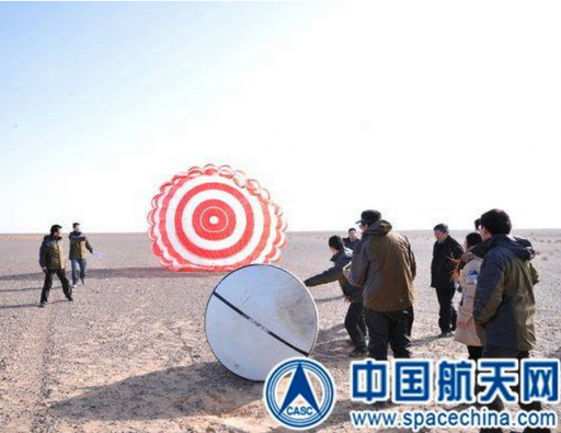
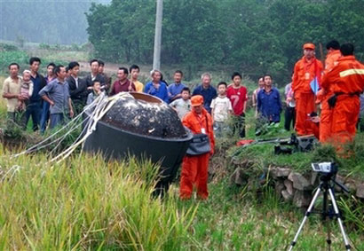
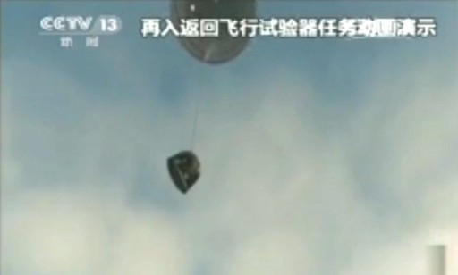
At an altitude of 10 Kilometers at a subsonic speed, the return vehicle will jettison its parachute cover and deploy a drogue chute that stabilizes the descent and dissipates horizontal velocity to make it safe to release the main chute. Descending under the main chute, the craft reduces horizontal velocity to zero and descends vertically until reaching the ground.
Chang’e 5-T1 is targeting a landing site near Huofutan in Inner Mongolia, close to the landing sites used by the Shenzhou missions. Beacon signals and tracking of the entry will lead recovery forces to the landed vehicle.
4M Radio Experiment
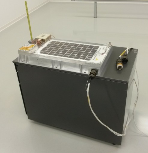
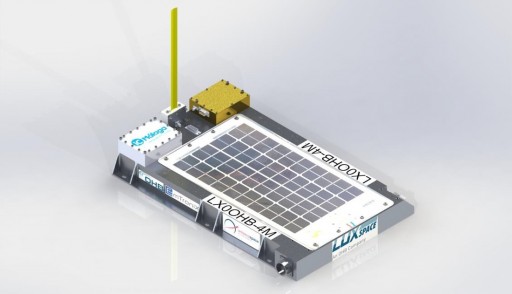
Traveling around the Moon alongside Chang’e 5-T1 is the 4M Radio Experiment developed by LUX Space and installed on the third stage of the Long March 3C/E rocket. 4M stands for Manfred Memorial Moon Mission, named after the late Professor Manfred Fuchs, founder of the OHB Group of which LUX Space is a member.
The 4M payload is installed in the Vehicle Equipment Bay of the third Stage of the Long March rocket. It weighs about 14 Kilograms consisting of a primary power source, a secondary power generation system, an onboard computer, a communications payload with modulator, amplifier and antenna, and a radiation experiment to study the dose received on a trans-lunar trajectory.
The primary power source consists of 28 high-density battery cells (29-35Wh per cell) that can not be recharged to guarantee a minimum mission duration of 100 hours. The payload consumes 6 Watts of power that can also be generated by an array of triple-layer solar cells that charge four Li-Ion batteries which could allow the instrument to keep operating beyond the exhaustion of primary power. However, since the third stage will no longer be active and without attitude control, illumination of the cells will be a game of pure luck.
The FM430 onboard computer controls all instrument functions and generates the signals to be sent via the communications payload which operates in the amateur VHF band at 145.980MHZ (+/-2.9kHz) using an RF power of 1.5 Watts.
The system will operate a one-minute sequence that is repeated five consecutive times to increase the probability of reception due to uncertainties in third stage rotation. The one-minute sequence will include a 46.8-second segment during which the call sign and digital data is transmitted followed by several short segments that transmit battery voltage and temperatures. The JT65B sequence includes two clear-text messages “Hello World” and “Ni Hao Xinhua” plus different messages that were pre-programmed as well as RAD and CAM data along with basic instrument parameters.
A number of experiments will be run with 4M including basic ranging and radiation dose assessments. The RAD detector will sent accumulated dose measurements that are expected to reach 74 to 100kRad over the course of the mission experiencing a dose rate of 13 to 16 Rad/hour.
The ranging experiment will require at least four ground stations receiving the 4M signal simultaneously making use of the time-stamps on the reception of the call sign (LX0OHB-4M) by the four different stations which can then be used to determine the TODA, the Time Difference of Arrival of the callsign. Since amateur equipment is used, the measurement will rely on the accuracy of the PC clocks of the receiving stations which will lead to a position error of around 5000 Kilometers.
The overall goal of 4M is to engage the amateur radio community in a unique circumlunar mission, assess this type of communication for future application in space, study the radiation environment on the way to the Moon and demonstrate a very basic ranging method.
The 4M payload becomes active 77.8 minutes after launch and will continue sending data until exhausting its primary power supply. The availability of solar power will depend on the attitude of the stage and its rotation rate. Additionally, the final trajectory of the third stage after the lunar flyby will depend on its insertion accuracy. It is probable (90%) that the stage re-enters the atmosphere after its flight around the Moon, but it could also enter a highly elliptical orbit with an apogee near 400,000 Kilometers.